

Home
>
Product > Electronic Appliances and Instruments > Environmentally Friendly Appliances > Electric Mosquito Repeller moulding
Product
- Core Customization Service
- Health Care
- Electronic Appliances and Instruments
- Maternal and Child Supplies Molds
- Recreational Sports
- Home Furnishing Art
- Auto Accessories
- Transportation and Warehousing
- Lighting Fixtures
- Construction Equipment
- Packaging Product
- Educational & Laboratories
- Clothing Luggage Accessories
- Care and Cleaning Products
- Agriculture & Forestry
- Mechanical Equipment
- Pet Supplies
- Kitchenware


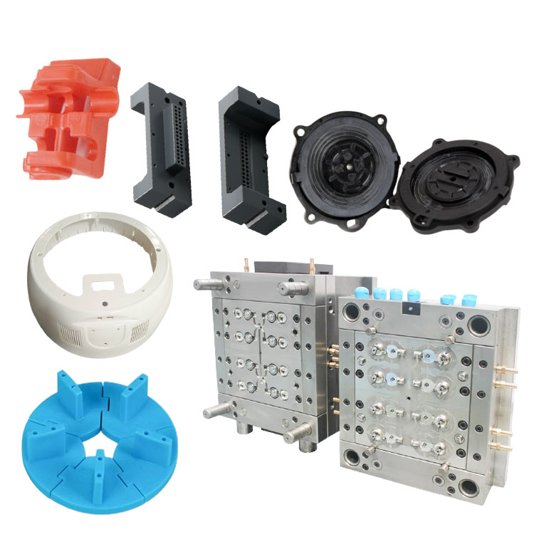
Electric Mosquito Repeller moulding
Ningbo (P&M) Plastic Metal Products Co., Ltd. has 17 years of mold manufacturing technology and can customize Electric Mosquito Repeller moulding. We provide professional customized Electric Mosquito Repeller moulding services, and we are a professional Electric Mosquito Repeller moulding manufacturer. We have sufficient experience in selecting product raw materials and mold materials. In the process of customizing Electric Mosquito Repeller moulding, our factory can provide one-stop service. We have design and production capabilities related to Electric Mosquito Repeller moulding, such as: CAD design, mold manufacturing, injection molding, plastic product production, assembly and other technologies.
Send Inquiry
Product Description
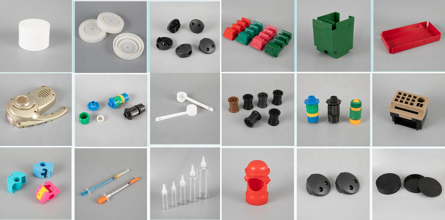
In addition, our company has established cooperative relationships with plastic raw material suppliers, printing manufacturers, etc. to ensure the supply of raw materials and printing quality. Through our rich experience and perfect supply chain, our company can provide customers with high-quality customized Electric Mosquito Repeller moulding products to meet their specific needs. At the same time, we have 10 years of professional foreign trade service experience, understand the foreign trade process, and better serve our customers. For Electric Mosquito Repeller moulding products, we can make corresponding plastic parts, which is mainly done through injection molds.


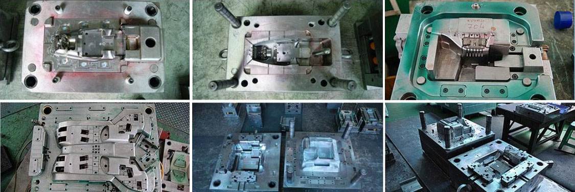
The core principles governing the mold manufacturing process for electric mosquito repellents are: aligning with product functionality, ensuring precision and stability, enhancing production efficiency, and extending mold lifespan. The entire process can be broadly divided into seven core stages: preliminary preparation and product analysis; mold design; mold material preparation and pre-treatment; precision machining of mold components; mold assembly; mold trial and debugging; and mold acceptance and delivery. Each stage is intricately linked; the quality of the preceding stage directly impacts the progress of subsequent steps. Any oversight in a single stage could result in the mold being scrapped or the final products failing to meet quality standards. Therefore, it is imperative to adhere to standardized operational protocols throughout the entire process, tailoring all tasks to the specific characteristics of the electric mosquito repellent product.
Stage 1: Preliminary Preparation and Product Analysis. This constitutes the fundamental prerequisite for mold manufacturing; its core objective is to clearly define product requirements and thoroughly analyze the product structure, thereby providing a scientific basis for subsequent mold design and machining. First, the mold manufacturing team must interface with the product design team to obtain comprehensive product documentation for the electric mosquito repellent. This includes 3D product models, 2D engineering drawings, material specifications, dimensional tolerances, aesthetic standards, assembly requirements, and functional parameters. Particular attention must be paid to dimensional tolerances; for critical areas—such as the housing seams, mounting holes for heating elements, and interfaces for liquid repellent bottles—tolerances are typically required to be controlled within ±0.02 mm. This strict control prevents issues such as excessive gaps in the housing seams, loose heating element mountings, or liquid leakage caused by dimensional deviations. Concurrently, the specific product materials must be clearly defined. The housing of the electric mosquito repellent is typically manufactured using ABS plastic, which is non-toxic, odorless, possesses high mechanical strength, is easy to mold, and exhibits sufficient heat resistance—making it suitable for products exposed to low-temperature thermal environments. The liquid repellent bottles or reservoirs are typically made of PP plastic, which offers excellent corrosion resistance and sealing properties, effectively preventing the leakage of the repellent liquid. Components that come into direct contact with the heating element—such as the heating base—may utilize PC plastic or modified ABS plastic, which offer superior heat resistance, thereby ensuring that the parts remain free from deformation or aging even after prolonged use.
During the product analysis phase, the primary focus is on deconstructing the structural characteristics of the electric mosquito repellent and, in conjunction with its functional requirements, analyzing the specific challenges associated with the molding process. For instance, the bottom housing of liquid-type electric mosquito repellents typically features a mounting slot for the liquid bottle, a perforation for the heating element rod, and an interface for the power cord. Some products also incorporate structural features such as indicator light mounting holes and button recesses. Notably, the liquid bottle mounting slot requires a high degree of sealing integrity to prevent leakage of the repellent fluid; consequently, the corresponding cavity within the mold must possess exceptional surface finish and dimensional precision. Furthermore, the positional accuracy of the perforation for the heating element rod is critical; excessive deviation in its placement could result in a tilted installation of the rod, thereby compromising both the heating performance and the efficiency of the repellent's volatilization. The top cover of electric mosquito repellent devices utilizing repellent mats typically features a dense array of ventilation holes—characterized by their minute diameters and uniform distribution. The mold design for such components necessitates the creation of corresponding slender core pins; simultaneously, careful consideration must be given to ensuring smooth demolding to prevent the core pins from fracturing or the finished product from exhibiting burrs. Moreover, the housings of certain electric mosquito repellent devices incorporate interlocking structures—such as snap-fits and slots—to facilitate the assembly and secure fastening of the upper and lower housing sections. To successfully mold these intricate features, the mold design must incorporate lateral core-pulling mechanisms; this requirement constitutes one of the primary challenges and critical focal points in the design and manufacturing of molds for electric mosquito repellent devices.
Concurrently, this phase necessitates the completion of market research and cost analysis. Based on the projected production volume of the product, a determination must be made regarding the appropriate mold configuration—specifically, whether to utilize a single-cavity mold or a multi-cavity mold. For large-scale production runs, multi-cavity molds are the preferred choice, as they can significantly enhance production efficiency; conversely, for smaller production batches, single-cavity molds are employed to minimize mold manufacturing costs. Furthermore, it is essential to systematically outline the key milestones, technical standards, and quality benchmarks for the mold manufacturing process. This entails formulating a comprehensive production schedule and clearly designating the individuals responsible for each specific stage, thereby ensuring that the mold manufacturing proceeds in an orderly and efficient manner.
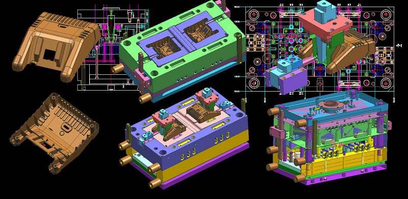
Phase Two: The Mold Design Stage. This constitutes the core phase of the mold manufacturing process, as it directly dictates the structural integrity, dimensional precision, and production efficiency of the finished mold. Drawing upon the findings derived from the preliminary product analysis, the design work is executed using specialized mold design software packages (such as UG, Pro/E, AutoCAD, etc.). Within this context, the "Mold Wizard" module of the UG software is widely utilized in the design of molds for electric mosquito repellent devices, enabling the efficient execution of critical tasks such as the design of parting lines and the modeling of mold cavities and cores. The mold design process must strictly adhere to a set of guiding principles: "structural soundness, adherence to precision standards, smooth demolding functionality, and ease of maintenance." Functionally, this phase is subdivided into two distinct components: molding process design and mold structure design. Molding process design serves as the foundation of mold design; it requires determining specific molding process parameters based on the material, structure, and dimensions of the electric mosquito repellent components. For instance, the molding temperature for ABS plastic is typically controlled within the range of 180–220°C, with an injection pressure of 80–120 MPa and a mold temperature of 50–60°C; if a high surface gloss is required for the product, the mold temperature may be raised to 60–80°C. For PP plastic, the molding temperature is 170–210°C, the injection pressure is 70–100 MPa, and the mold temperature is controlled at 20–40°C. Concurrently, the material's shrinkage rate must be analyzed: ABS plastic typically exhibits a shrinkage rate of 0.5%–0.8%, while PP plastic has a rate of 1.0%–2.0%. When designing the mold cavity, appropriate allowances must be incorporated based on these shrinkage rates to ensure that the dimensions of the molded product meet the design specifications. Furthermore, a design scheme for the gating system must be established; since the components for electric mosquito repellents are predominantly small, thin-walled parts, the gating system should utilize a fine-gate design to prevent gate marks from compromising the product's aesthetic appeal, while simultaneously ensuring smooth melt flow and minimizing molding defects such as weld lines and sink marks. For components featuring ventilation holes or intricate perforations, a well-engineered venting system is essential to facilitate the timely evacuation of gases generated during the molding process, thereby preventing defects such as air bubbles and short shots.
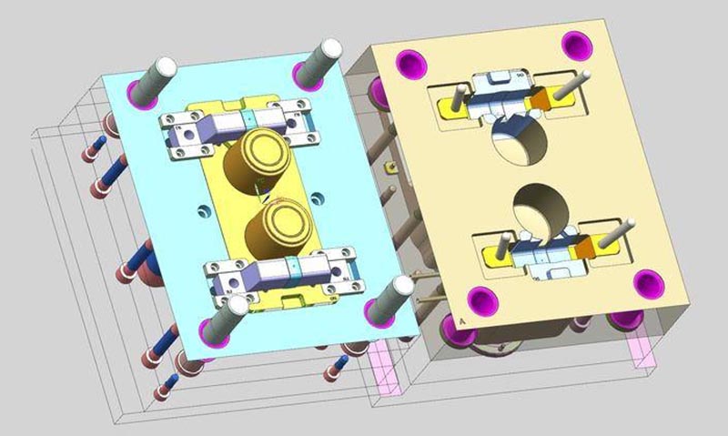
Mold structure design constitutes the core of the design phase; it entails integrating the product's structural configuration with the molding process requirements to complete the overall mold structure design—encompassing the design of the cavity, core, mold base, guiding mechanism, ejection mechanism, side-core pulling mechanism, cooling system, and other constituent parts. The cavity and core serve as the mold's primary forming components; their geometry must precisely replicate the external contours of the electric mosquito repellent components. Given the extremely high precision requirements involved, these components must be modeled with exacting accuracy based on the product's 3D digital model. Moreover, the surface roughness of these components must achieve a standard of Ra 0.12 μm or finer to ensure that the resulting molded product possesses a smooth, burr-free surface finish. As the foundational framework of a mold, the mold base must be selected to possess sufficient strength and excellent rigidity; the most commonly used material for mold bases is 45 steel. After undergoing quenching and tempering treatment, its hardness and wear resistance are enhanced, thereby ensuring that the mold remains free from deformation during prolonged use.
The guiding mechanism serves to ensure precise alignment when the mold closes, preventing misalignment between the upper and lower mold halves that could result in product rejection. Typically, this is achieved through a combination of guide pillars and guide bushings; the clearance between the pillars and bushings must be strictly controlled within a range of 0.01–0.03 mm. Additionally, locating pins must be incorporated to further enhance positioning accuracy. The ejection mechanism is responsible for demolding the product once it has been formed. The appropriate ejection method must be selected based on the specific structural characteristics of the product. For the housing of electric mosquito repellents, pin ejection is frequently employed; the placement of the ejector pins must be carefully positioned to avoid critical functional areas and visible exterior surfaces of the product, thereby preventing the appearance of unsightly ejection marks. For components featuring more complex geometries, methods such as stripper plate ejection or angled pin ejection may be utilized to ensure smooth demolding without causing damage to the product.
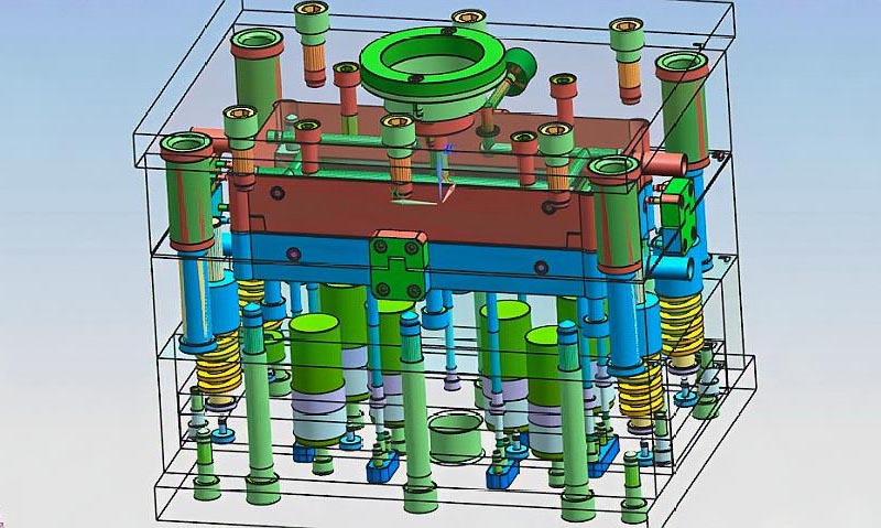
The lateral core-pulling mechanism constitutes a critical focal point in the design of molds for electric mosquito repellents. Its primary function is to form lateral features on the product—such as snap-fit tabs, slots, and side holes—examples of which include the side aperture for the power cord on the bottom housing and the various snap-fit tabs on the outer casing. A commonly adopted method is the angled guide pin core-pulling mechanism. Its design requires precise calculations regarding the inclination angle, length, and stroke distance of the angled guide pins to ensure both smooth core retraction and accurate return to the home position. Furthermore, a locking mechanism must be incorporated to prevent any inadvertent shifting of the lateral cores during mold closure, which could otherwise compromise the dimensional accuracy of the final product. The cooling system is designed to regulate the mold temperature, facilitating the rapid cooling and solidification of the molten material to boost production efficiency while simultaneously minimizing product shrinkage and deformation. The cooling channels must closely follow the contours of both the mold cavity and the core, ensuring a uniform distribution that maintains a consistent temperature across all parts of the mold. For components requiring a high degree of airtightness—such as liquid repellent bottles—the cooling system design demands even greater precision to prevent uneven cooling from inducing product warping or deformation. Upon completion of the design phase, the mold design scheme must undergo a comprehensive review. This involves utilizing CAE mold flow analysis technology to simulate the entire process of melt filling, cooling, and shrinkage. By predicting potential defects that may arise during the molding process—such as weld lines, sink marks, and warping—the mold structure and process parameters can be optimized based on the analysis results, thereby reducing the number of mold trials and lowering mold manufacturing costs. Concurrently, detailed mold assembly drawings and component machining drawings must be drafted, clearly specifying the dimensions, tolerances, materials, and machining requirements for each individual part to provide a definitive basis for subsequent manufacturing and assembly operations.
Phase III: Mold Material Preparation and Pre-treatment. The selection and pre-treatment of mold materials directly impact the mold's hardness, wear resistance, service life, and machining precision. Therefore, based on the specific operational requirements and machining complexity of the electric mosquito repellent mold, appropriate materials must be selected and subjected to rigorous pre-treatment. Core mold components—such as cavities, cores, angled guide pins, and ejector pins—require the use of high-strength, high-wear-resistance mold steels. Commonly used options include pre-hardened steels such as P20, 718H, and NAK80. Among these, P20 steel offers excellent machinability and comprehensive mechanical properties, reaching a hardness of HRC 30–36; it is suitable for electric mosquito repellent molds requiring standard precision. 718H steel possesses higher hardness (HRC 38–42), along with superior wear resistance and toughness, making it ideal for molds intended for high-volume production or those with stringent precision requirements. NAK80 steel is a pre-hardened, polishable steel capable of achieving a high surface finish without the need for subsequent polishing treatments; it is best suited for molds where the aesthetic quality of the final product is a critical requirement. Auxiliary components—such as mold bases, guide pillars, and guide bushings—may be fabricated using 45# steel or 40Cr steel, which undergo quenching and tempering treatments to enhance their strength and rigidity.
Once material preparation is complete, the pre-treatment phase commences, primarily involving processes such as forging, annealing, and quenching and tempering. The objective of forging is to refine the internal microstructure of the material, eliminate defects such as porosity and looseness, and enhance the material's density and toughness, thereby ensuring that mold components do not fracture during subsequent machining or operational use. The objective of annealing is to reduce material hardness, improve machinability, and minimize tool wear during processing, while simultaneously relieving internal stresses to prevent deformation during subsequent machining and heat treatment stages. For mold steels, spheroidizing annealing is typically employed; the material is heated to 750–780°C, held at this temperature for a specific duration, and then slowly cooled. This process transforms the internal microstructure into spheroidized pearlite, reducing the hardness to HB 200–220 and thereby facilitating subsequent cutting operations. Quenching and tempering—a heat treatment process primarily applied to mold bases and auxiliary components—involves heating the material to 850–880°C, holding it at this temperature before quenching, and then reheating it to 550–600°C for tempering. This process imparts excellent strength and toughness to the material, with the hardness controlled within the range of HRC 28–32, thereby ensuring the rigidity and stability of the mold base.
Upon completion of the pretreatment phase, the material must undergo dimensional inspection and surface quality assessment to ensure that its dimensions meet processing specifications and that its surface is free from defects such as cracks, scratches, or scale. Any non-conforming materials must be promptly replaced to prevent any adverse impact on the quality of subsequent processing stages.
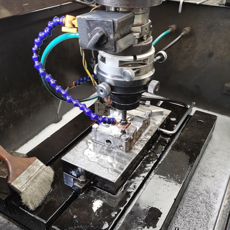
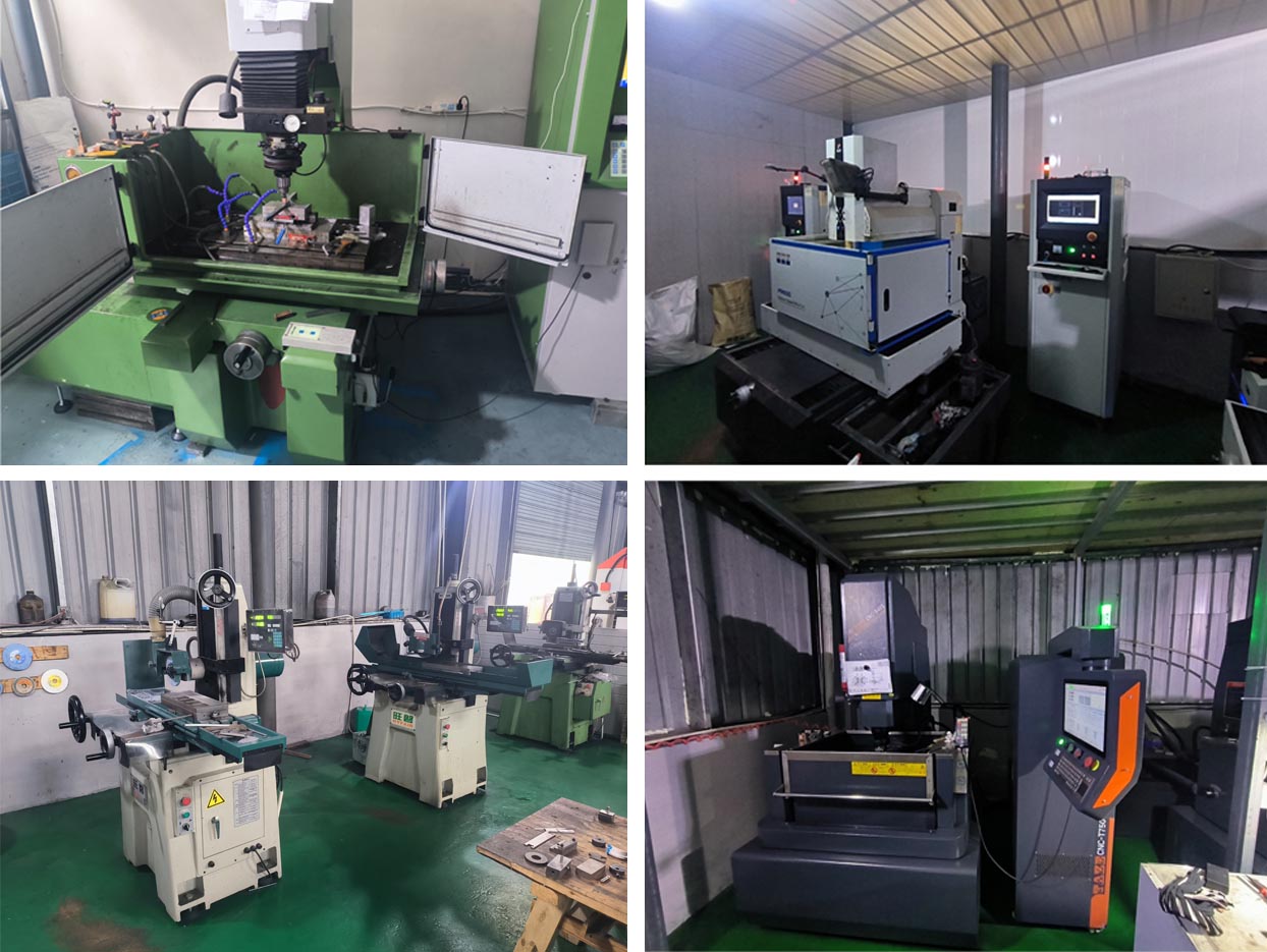
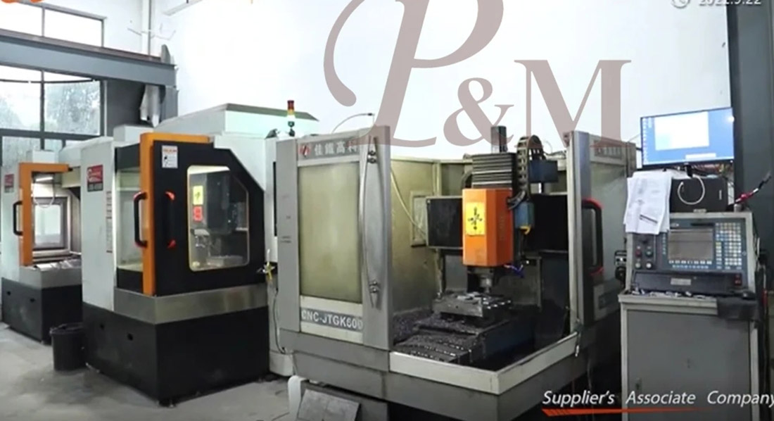
Phase 4: Precision Machining of Mold Components. This constitutes the critical stage where the design blueprint is translated into tangible physical components. Based on the specific processing requirements of each mold component, appropriate machining equipment and techniques must be selected, with strict controls applied to ensure machining precision and surface quality. The components for the electric mosquito repellent mold demand high machining precision and involve complex processing sequences, primarily comprising rough machining, semi-finishing, finishing, and surface treatment stages. Commonly utilized equipment for these operations includes CNC milling machines, CNC lathes, Electrical Discharge Machining (EDM) machines, Wire Electrical Discharge Machining (WEDM) machines, grinding machines, and polishing machines.
The primary objective of the rough machining phase is to remove excess material and establish the preliminary contour of the component, thereby laying the foundation for subsequent finishing operations. Rough machining is typically performed using CNC milling machines or conventional milling machines. During this process, a finishing allowance of 0.3–0.5 mm must be reserved; furthermore, machining speeds and feed rates must be carefully controlled to prevent material deformation caused by excessive machining-induced stresses. For components featuring complex geometries—such as mold cavities and cores—an aging treatment is performed following rough machining to relieve internal stresses and further minimize the potential for deformation during the subsequent finishing stages. The semi-finishing stage primarily involves refining the contours of components and correcting errors generated during rough machining, thereby bringing the dimensions and geometry of the parts closer to design specifications. Semi-finishing operations typically utilize equipment such as CNC milling machines and CNC lathes, maintaining a machining tolerance within ±0.05 mm. Concurrently, critical areas of the components undergo preliminary deburring to remove machining burrs. For components featuring complex curved surfaces or intricate micro-structures—such as the vent core pins in the upper cover of an electric mosquito repellent device, or the angled guide pillars within a side-core pulling mechanism—the semi-finishing stage necessitates the use of high-precision CNC machining equipment to ensure the dimensional accuracy of these structural features.
The finishing stage constitutes the pivotal phase for guaranteeing mold precision; it demands the deployment of high-precision machining equipment and rigorous control over both machining accuracy and surface quality. For core components such as mold cavities and cores, finishing operations may employ equipment including 5-axis simultaneous CNC milling machines, Electrical Discharge Machining (EDM) machines, and Wire-cut EDM machines. Among these, 5-axis simultaneous CNC milling machines enable high-precision machining of complex curved surfaces, achieving a machining tolerance of up to ±0.005 mm and a surface roughness of Ra 0.08 μm. EDM machines are primarily utilized to machine complex structures and intricate features within cavities and cores; by utilizing spark discharges between an electrode and the workpiece to erode metal material, they achieve a machining tolerance of up to ±0.002 mm and are capable of processing high-hardness mold steels. Wire-cut EDM machines are predominantly used to machine components such as mold inserts and angled guide pillars, enabling high-precision machining of both linear and curved profiles; specifically, slow-feed wire-cut EDM can achieve a machining tolerance of up to ±0.001 mm and a surface roughness of Ra 0.05 μm.
Upon the completion of the finishing stage, the components undergo surface treatment processes, primarily including polishing and nitriding. The objective of polishing is to enhance the surface finish of the components, thereby ensuring that the resulting molded products possess smooth, scratch-free surfaces. The polishing process requires the progressive use of increasingly finer polishing tools—ranging from rough polishing to fine polishing—until the surface roughness of the mold cavities and cores reaches a standard of Ra 0.12 μm or better. For components requiring a high degree of sealing integrity—such as liquid medicine bottles—the surface roughness must meet an even more stringent standard of Ra 0.08 μm or better. Nitriding treatment is primarily employed to enhance the surface hardness and wear resistance of mold components, thereby extending the mold's service life. Typically, a gas nitriding process is utilized: components are placed in a nitriding furnace where, at a temperature of 500–550°C, ammonia gas is introduced. This causes nitrogen atoms to diffuse into the component surfaces, forming a hard nitrided layer with a surface hardness exceeding HV850. Crucially, this process does not compromise the internal toughness of the components, thereby preventing wear and deformation during operation.
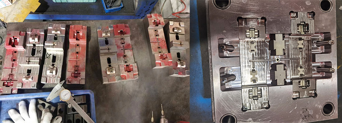
Throughout the manufacturing process, every component undergoes rigorous quality inspection. Inspection equipment—such as calipers, micrometers, dial indicators, and coordinate measuring machines (CMMs)—is used to verify dimensions, tolerances, surface roughness, and other parameters, ensuring strict compliance with design specifications. Non-conforming components are either reworked or scrapped to prevent them from proceeding to the subsequent assembly stage.
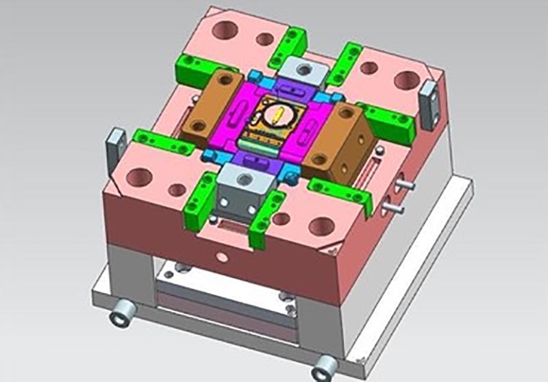
Stage 5: Mold Assembly. Mold assembly is the process of integrating the various finished components into a complete mold in accordance with design specifications. Assembly precision directly impacts the mold's closing accuracy, ejection smoothness, and overall production efficiency. Consequently, the assembly process adheres to the principles of "installing datum features first, followed by details; and installing internal components first, followed by external ones." This involves utilizing specialized assembly tools and techniques to maintain strict control over assembly quality.
Prior to assembly, all components undergo a thorough cleaning process to remove surface contaminants—such as oil stains, metal chips, and dust—which could otherwise compromise assembly precision and the mold's service life. Concurrently, the dimensions and surface quality of each component are inspected to ensure they meet specifications before assembly commences. The initial step of assembly involves installing the mold base; this entails assembling components such as the upper and lower mold plates, guide pillars, and guide bushings. The clearance between the guide pillars and bushings is carefully adjusted to ensure smooth, snag-free mold closing and precise alignment. The installation of the guide pillars and bushings typically utilizes an interference fit to ensure a secure connection, and a lubricant is applied to their mating surfaces to facilitate smooth operation.
...oil to reduce wear.
Next, the cavity and core are installed. The machined cavity and core are secured to the mold base using either bolted connections or press-fits, ensuring a firm, wobble-free attachment. The installation of the cavity and core must strictly adhere to the design specifications; their coaxiality and flatness must be adjusted to ensure precise mating during mold closure, thereby preventing misalignment that could result in scrapped products. Upon completion of the installation, the mating clearance between the cavity and core must be inspected. This clearance should be maintained within a range of 0.01–0.03 mm to prevent molten material leakage while avoiding excessive compression that could damage the components.
Subsequently, auxiliary mechanisms—such as the ejection system, side-core pulling mechanism, cooling system, and gating system—are installed. For the ejection system, the position and height of the ejector pins must be adjusted to ensure they eject the product smoothly and return accurately to their home position after ejection. The clearance between the ejector pins and their corresponding holes must be controlled within 0.01–0.02 mm to prevent material leakage. For the side-core pulling mechanism, the inclination angle of the angled guide pins and the core-pulling stroke must be adjusted to ensure smooth extraction and accurate return; the locking mechanism must be securely fastened to prevent the side core from shifting during mold closure. For the cooling system, all pipeline connections must be secured and leak-free, and the contact between the pipelines and the cavity/core must be optimized to ensure uniform cooling efficiency. For the gating system, the position and dimensions of the gate must be adjusted to ensure smooth filling of the molten material and a seamless transition between the gate and the cavity, thereby minimizing gate marks.
Once assembly is complete, a comprehensive debugging process is required. The mold is manually opened and closed to verify its closing precision, ejection smoothness, and the synchronized operation of all mechanisms, ensuring that the mold functions correctly. Concurrently, the mold's sealing integrity must be verified through pressure testing to confirm that the cooling and gating systems are free of leaks. Any issues identified during this process must be promptly addressed through adjustments or rework until the mold assembly meets all quality standards. Phase 6: Mold Trial and Debugging. This constitutes a critical stage for verifying the quality and performance of the mold. During this phase, sample parts are produced through trial runs; these samples are then inspected for various metrics—including dimensions, appearance, and functionality. Based on the results of the mold trial, adjustments are made to the mold itself as well as to the process parameters, thereby ensuring that the mold is capable of producing compliant products. Mold trials must be conducted on dedicated injection molding machines or die-casting machines, with the equipment parameters—such as injection pressure, injection speed, molding temperature, mold temperature, and cooling time—configured in strict accordance with the molding process parameters established during the initial design phase.
|
Product Name |
Treadmill moulding |
|
Pls provide |
2D, 3D, samples, or the size of the multi-angle pictures |
|
Mould Time |
20-35 Days |
|
Product time |
7-15 Days |
|
Mould precision |
+/-0.01mm |
|
Mould life |
50-100 million shots |
|
Producing Process |
Audit drawings - mold flow analysis - design validation - Custom Materials - mold processing - core processing - electrode machining - Runner system processing - parts processing and procurement - machining acceptance - cavity surface treatment process - complex mode Die - The entire mold surface coating - Mounting plate - mold sample - sample test - sending samples |
|
Mould cavity |
One cavity, multi-cavity or same different products be made together |
|
Mould material |
P20,2738,2344,718,S136,8407,NAK80,SKD61,H13 |
|
Runner system |
Hot runner and cold runner |
|
Base material |
P20,2738,2344,718,S136,8407,NAK80,SKD61,H13 |
|
Finish |
Pitting the word, mirror finish, matte surface, striae |
|
Standard |
HASCO, DME or dependent upon |
|
Main technology |
Milling, grinding, CNC, EDM, wire cutting, carving, EDM, lathes, surface Finish, etc. |
|
Software |
CAD,PRO-E,UG Design Time: 1-3 days (normal circumstances) |
|
Product material |
ABS,PP,PC,PA6,PA66,TPU,POM,PBT,PVC,HIPS,PMMA,TPE,PC/ABS,TPV,TPO,TPR,EVA,HDPE,LDPE,CPVC,PVDF,PPSU.PPS. |
|
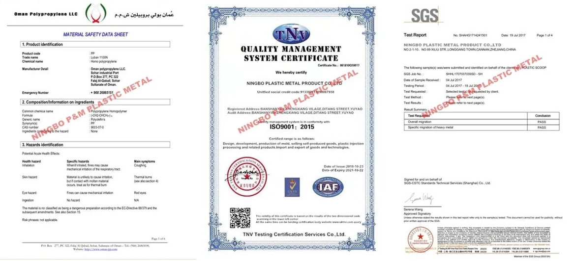
Quality system |
ISO9001:2008 |
|
Establish time |
20days |
|
Equipment |
CNC,EDM,Cutting off Machine,plastic machinery,etc plastic suitcase mould zhe jiang |
Plastic Injection Mould making
Plastic molding specifications
Mold design:
Transaction process:
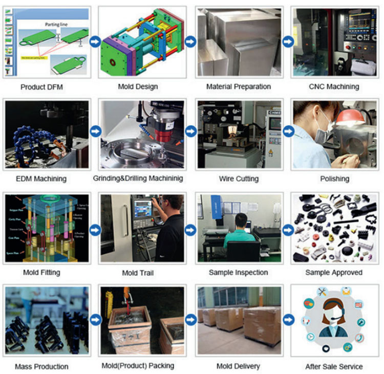
Mold testing:

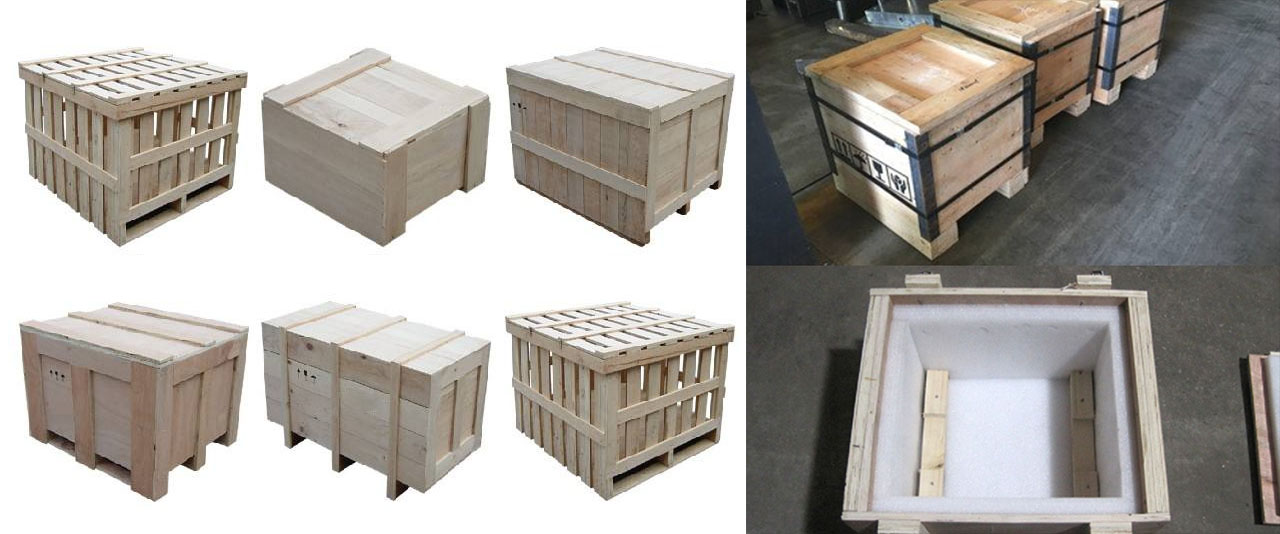
Product packaging
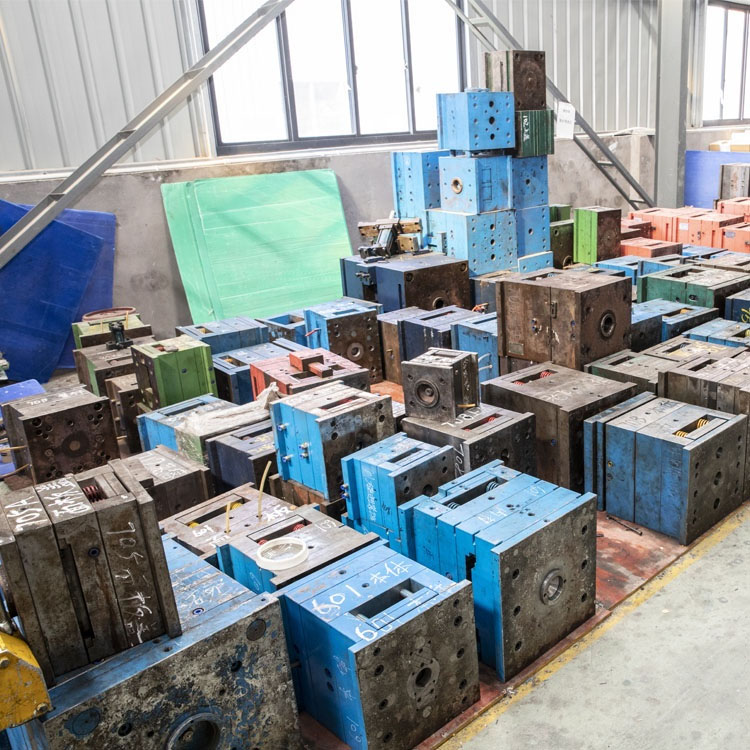
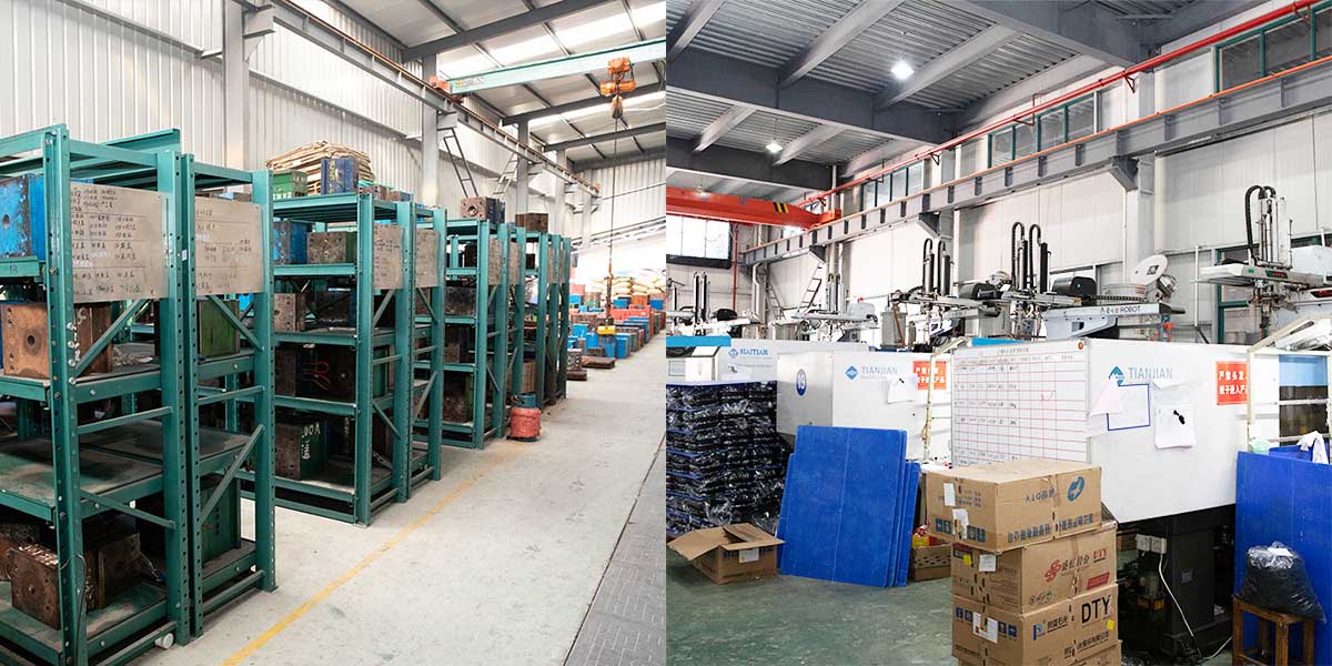
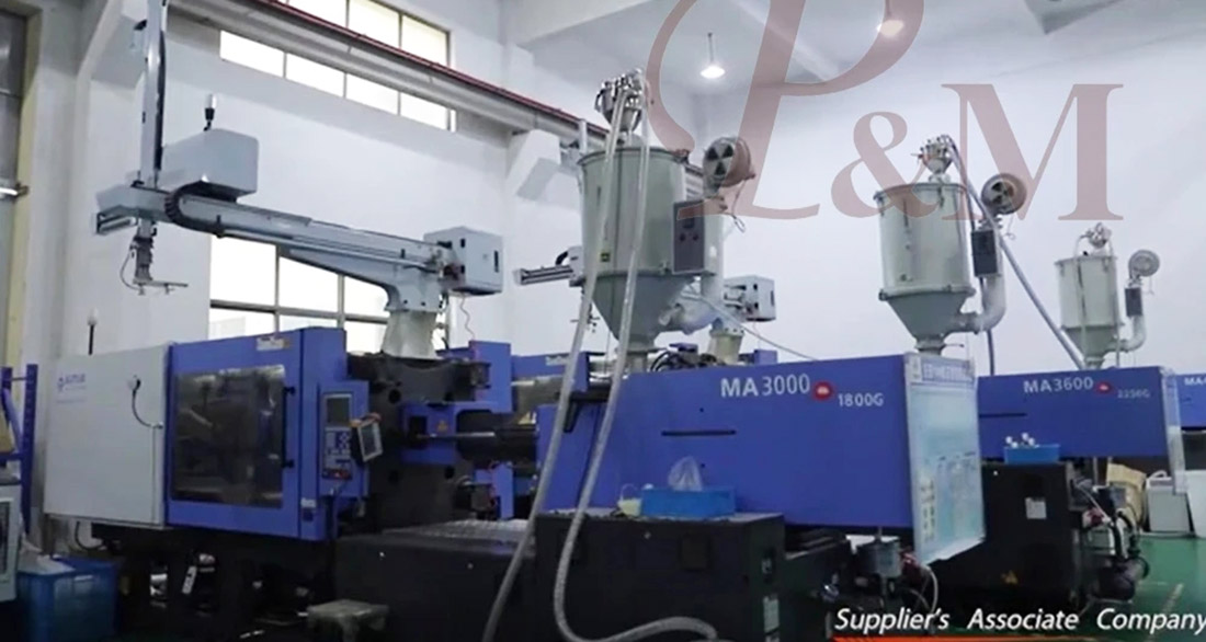
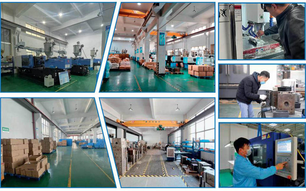
Factory
We are Custom Plastic Mold factory. Our factory is plastic injection mold maker. we has 17 years of experience in professional custom plastic mold and 10 years of foreign trade experience. We are custom Plastic Mold supplier. We can provide custom Plastic Mold service. Our factory can make the Injection molded plastic parts, and the quality of the products will satisfy you.
We have more than 50 high-end machines and hundreds of engineers and designers. We can provide one-stop service, from product design - mold making - product production - product packaging - transportation. We have a complete production chain. We can meet all your requirements.
Services we provide:
Professional custom mold service, Plastic mold design and manufacturing .plastic product production, product design, mold design, blow mold customization, rotational mold customization, die-casting mold customization. 3D printing services, CNC manufacturing services, product packaging, customized packaging, shipping services.


We always adhere to the principles of quality first and time first. While providing customers with the highest quality products, try to maximize the production efficiency and shorten production time. We are proud to tell every customer that our company has not lost any customer since its establishment.If there is a problem with the product, we will seek a solution actively and take responsibility to the end.

FAQ
Q1: Are you trading company or manufacturer ?
A: We are manufacturers.
Q2. When can I get the quotation?
A: We usually quote within 2 days after we get your inquiry.
If you are very urgent, please call us or tell us in your email so that we can quote for you first.
Q3. How long is the lead-time for mold?
A: It all depends on the products' size and complexity. Normally, the lead time is 25 days.
Q4. I have no 3D drawing, how should I start the new project?
A: You can supply us a molding sample, we will help you finish the 3D drawing design.
Q5. Before shipment, how to make sure the products quality?
A: If you don't come to our factory and also don't have the third party for inspection, we will be as your inspection worker.
We will supply you a video for production process detail include process report, products size structure and surface detail, packing detail and so on.
Q6. What is your payment terms?
A: Mold Payment: 40% deposit by T/T in advance, 30% second mold payment before sending out the first trial samples, 30% mold balance after you agree the final samples.
B:Production Payment: 50% deposit in advance, 50% before sending out the final goods.
Q7: How do you make our business long-term and good relationship?
A:1. We keep good quality and competitive price to ensure our customers benefit for best quality products.
2. We respect every customer as our friend and we sincerely do business and make friends with them, no matter where they come from.
Hot Tags: Electric Mosquito Repeller moulding, China, Manufacturer, Supplier, Factory, Customized, Wholesale, Buy, Quality, Latest Selling, Made in China
Related Category
Audio-Visual Appliances
Health Appliances
Home Appliances
Personal Necessities
Digital Appliances
Kitchen Appliances
Bathroom Appliances
Environmentally Friendly Appliances
Send Inquiry
Please feel free to give your inquiry in the form below. We will reply you in 24 hours.