

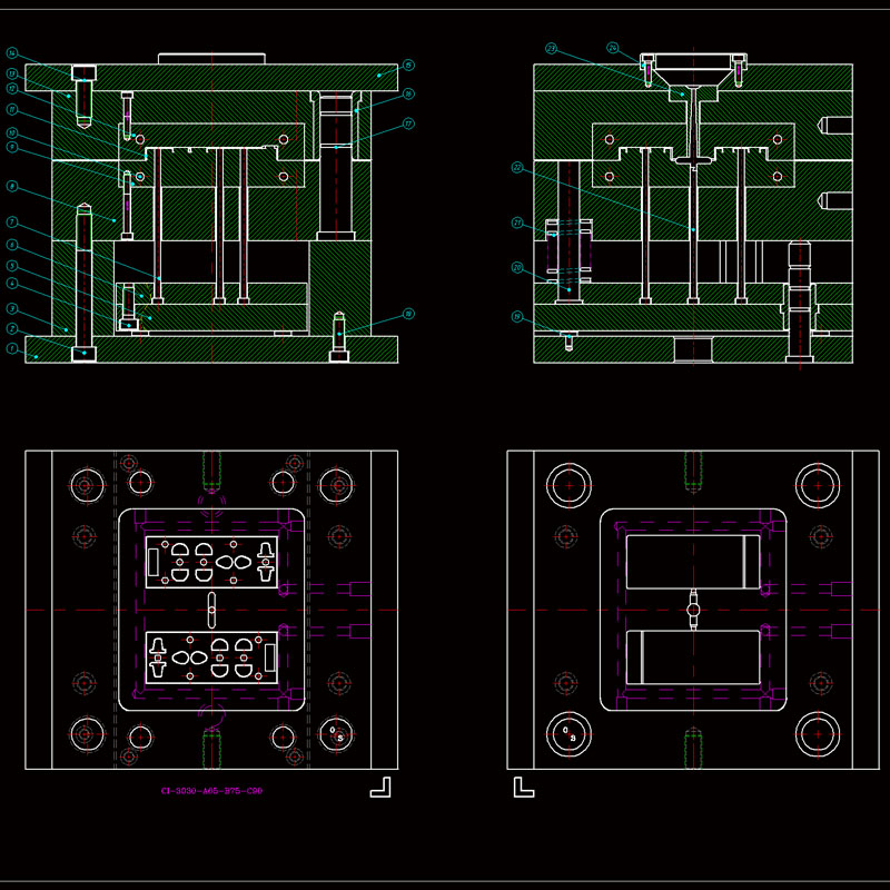
Key points of injection mold design
Injection mold drawing design is the core link of mold manufacturing, which needs to comprehensively consider processability, structural rationality and production cost. The following are key points and detailed descriptions:
1. Product analysis and preliminary preparation
Product structure evaluation
Draft angle: usually 1°~3°, to avoid demoulding damage; deep cavity or texture surface needs to be appropriately increased.
Wall thickness uniformity: avoid shrinkage marks (recommended 2~4mm, thin-walled parts not less than 0.5mm).
Undercut processing: solved by slider, inclined top or hinge structure, the movement space needs to be marked.
Example: inclined top mechanism is commonly used for side holes of mobile phone cases, and the stroke needs to be greater than 2mm of undercut depth.
Material property matching
Shrinkage compensation (such as ABS about 0.5%, PP about 1.5%), mark the dimensional tolerance in the drawing (such as ±0.05mm).
Parting line design needs to avoid appearance surface, and give priority to plane or regular surface.
2. Core elements of mold structure design
Parting surface design
Select the maximum contour line to reduce flash; complex parting surface needs to use 3D surface transition.
Consider processing feasibility (such as EDM or CNC process marking).
Casting system optimization
Cold runner: main runner taper 2°~5°, balanced layout of branch runner (circular/trapezoidal cross section).
Hot runner: mark the control point of the heating zone to avoid melt retention (such as needle valve timing control).
Cooling system layout
Follow the "equidistant principle" (10~15mm from the cavity surface), design spiral or stepped water channels, and mark the inlet and outlet directions.
Special-shaped parts are preferably equipped with conformal water channels, in conjunction with mold temperature controller parameters (such as PC materials require 80~120℃).
III. Ejection and exhaust system
Ejection mechanism
Ejector diameter ≥2.5mm, spacing ≤50mm; deep ribs require push plates or air caps.
The reset rod needs to have a preload spring (compression ≥10mm).
Exhaust design
The exhaust groove depth is 0.02~0.04mm (material dependent), located at the end of the melt or at the inlay.
Large molds are equipped with exhaust steel or vacuum systems.
IV. Drawing marking and processing requirements
Key dimension marking
Cavity/core matching tolerance (H7/h6), mold core hardness (HRC48~52).
Inserts need to be drawn separately, and the wire cutting or grinding process should be marked.
Standardization and DFM
The mold frame uses Longji standard (such as CI type), and the guide column diameter is 0.02mm smaller than the template.
Mark surface treatment (such as nitriding, chrome plating) and anti-rust requirements.
V. Design verification and cost control
CAE simulation application
Through Moldflow, fill balance and cooling efficiency are analyzed, and the gate position is optimized (such as banana gate to reduce shear).
Cost optimization
Simplify special-shaped inserts (such as using spark patterns instead of fine carving), and reserve mold repair margin for the mold core (0.1mm on one side).
Injection mold drawing design is the core link of mold manufacturing, and it is necessary to comprehensively consider processability, functionality, economy and maintainability. The following are the key points and step-by-step analysis:
1. Key points of structural design
Parting surface design
Location selection: give priority to the largest contour of the product to avoid undercuts; consider the demoulding slope (usually 1°~3°) and the quality of the appearance surface.
Sealing: The parting surface needs to fit tightly to prevent overflow (flash), and step parting or curved parting should be used when necessary.
Processing feasibility: ensure that the parting surface can be realized by CNC or EDM processing, and complex parting needs to be marked with 3D coordinates.
Cavity and core
Shrinkage compensation: adjust the cavity size according to the material (such as ABS shrinkage 0.5%~0.7%), and mark the tolerance (usually IT7~IT8).
Surface treatment: The high-gloss surface needs to be polished to Ra0.025μm, and the texture surface needs to be marked with etching requirements (such as VDI3400 standard).
Strength verification: calculate the effect of injection pressure (usually 30~80MPa) on the cavity wall thickness to avoid deformation.
2. Design of pouring system
Main channel and branch channel
Size matching: The diameter of the main channel is usually 4~8mm, and the cross-sectional shape of the branch channel is preferably trapezoidal or circular (diameter 3~6mm).
Cold well: set at the end of the main channel, length ≥1.5 times the diameter of the main channel.
Gate type selection
Side gate: suitable for most box-type parts, width is 2/3 of the wall thickness, length 0.5~1mm.
Point gate: used for transparent parts or high-precision parts, diameter 0.8~1.2mm, automatic demolding mechanism required.
Hot runner: mark the position and control parameters of the heating element to avoid degradation caused by melt retention.
3. Ejection and cooling system
Ejection mechanism
Ejector layout: evenly distributed at the force points of the product (such as rib position, BOSS column), diameter ≥2.5mm, spacing ≤50mm.
Reset device: spring reset needs to mark the preload, and mechanical reset needs to cooperate with the travel switch.
Cooling water channel
Layout principle: follow "conformal cooling", 10~15mm from the cavity surface, 8~12mm aperture.
Flow calculation: ensure that the Reynolds number is >4000 (turbulent state), and the parallel water channel needs to mark the flow balance valve.
IV. Detail marking and standardization
Drawing specification
View completeness: including main view, sectional view (showing ejection/cooling structure), and local enlarged view (such as gate details).
Tolerance marking: The matching tolerance of the movable mold and the fixed mold is H7/h6, and the key dimension tolerance is ±0.02mm.
Material and process notes
Mold core material: pre-hardened steel (such as P20) or quenched steel (such as H13), hardness HRC48~52.
Processing symbol: mark EDM, wire cutting or polishing area, and indicate the surface roughness.
V. DFM (Design for Manufacturing)
Mold stripping slope: appearance surface ≥1°, internal structure ≥0.5°, deep cavity parts need segmented slope.
Uniform wall thickness: avoid sudden changes (such as a sudden increase from 2mm to 5mm) to prevent shrinkage or warping.
Mold life: For glass fiber reinforced materials, wear-resistant coatings (such as TiAlN) need to be marked.
In injection mold design, the sealing of the parting surface directly affects product quality (such as flash, burrs) and mold life. The following are key design techniques and practical points:
1. Core design principles for parting surface sealing
Contact pressure optimization
Preload calculation: The contact pressure of the parting surface must be greater than the injection pressure (usually 30~80MPa), and the unit area pressure of the steel mold parting surface is recommended to be ≥100MPa.
Hardness matching: The hardness difference between the fixed mold and the movable mold is controlled within HRC 2~4 (such as fixed mold HRC52, movable mold HRC50) to avoid micro deformation and leakage caused by hardness difference.
Surface treatment process
Finishing requirements: The parting surface needs to be ground to Ra≤0.8μm, and ultra-precision molds (such as optical parts) need to be polished to Ra0.1μm or less.
Coating reinforcement: TiN coating is recommended for high glass fiber materials (such as PA+30% GF) to reduce the risk of seal failure caused by wear.
2. Parting surface structure design skills
Stepped/curved parting
Applicable scenarios: For complex contour products (such as automotive interior parts), multi-step parting is used to disperse the melt pressure, and the step height difference is recommended to be 0.1~0.3mm.
Avoidance design: 0.02~0.05mm avoidance is made in the non-sealed area to reduce the contact area to increase the local pressure (the principle is similar to O-ring sealing).
Clamping mechanism coordination
Chamfer locking: Add a 5°~10° chamfer on the outside of the parting surface to generate radial force to enhance the seal when the mold is closed (need to cooperate with the calculation of the chamfer self-locking angle).
Micro stopper: Design a 0.3~0.5mm stopper on the edge of the parting surface to cut off the melt flow path (similar to a labyrinth seal).
3. Material and process compensation design
Thermal deformation compensation
Temperature difference pre-correction: According to the mold temperature difference (such as 60℃ for fixed mold and 40℃ for movable mold), 0.02~0.05mm reverse warpage compensation is reserved on the parting surface.
Local reinforcement: Tungsten steel blocks (hardness HRA90) are inserted in the overflow area (such as near the gate) to resist thermal creep deformation.
Exhaust and sealing balance
Exhaust groove design: An exhaust groove with a depth of 0.02~0.04mm and a width of 5~10mm is opened at the end of the parting surface to exhaust gas and block the melt.
Vacuum adsorption: For large thin-walled parts (such as mobile phone shells), a vacuum channel (Φ1~2mm) can be set on the parting surface, and vacuum is drawn to enhance the seal when the mold is closed.
Previous:Introduction of mold carving