
Product
- Core Customization Service
- Health Care
- Electronic Appliances and Instruments
- Maternal and Child Supplies Molds
- Recreational Sports
- Home Furnishing Art
- Auto Accessories
- Transportation and Warehousing
- Lighting Fixtures
- Construction Equipment
- Packaging Product
- Educational & Laboratories
- Clothing Luggage Accessories
- Care and Cleaning Products
- Agriculture & Forestry
- Mechanical Equipment
- Pet Supplies
- Kitchenware
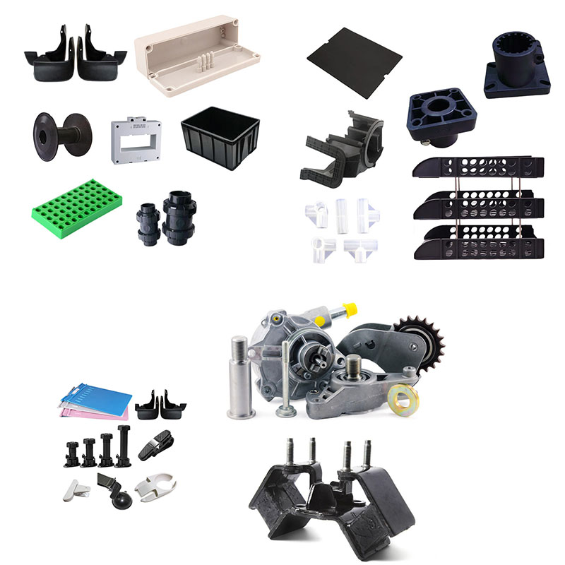
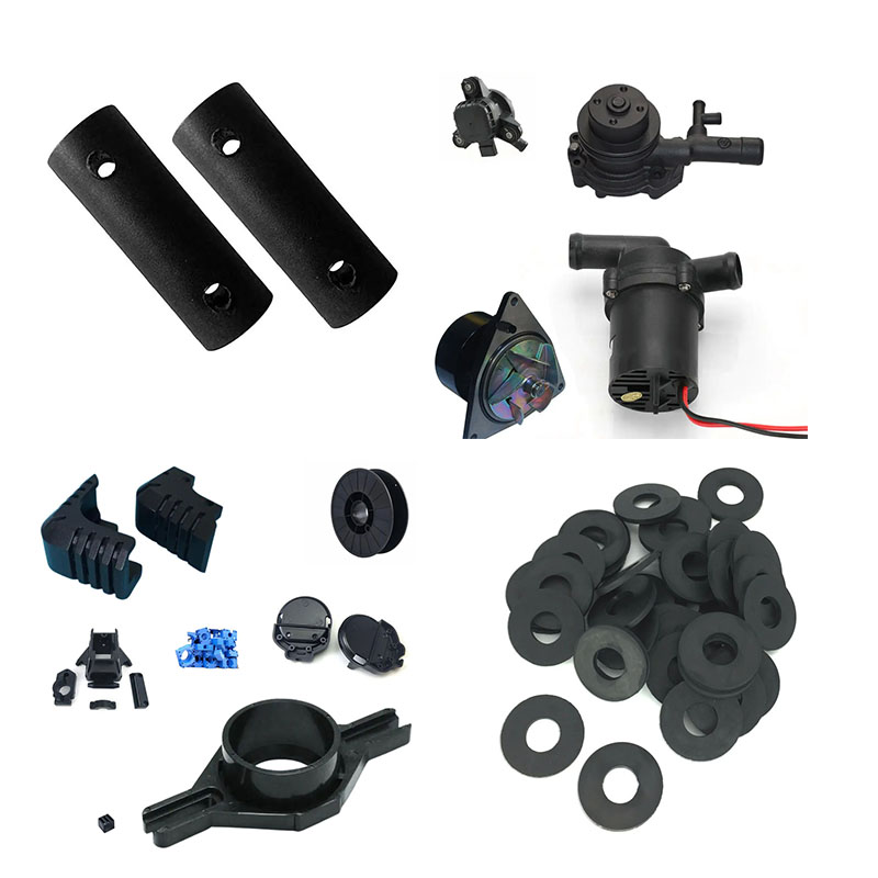
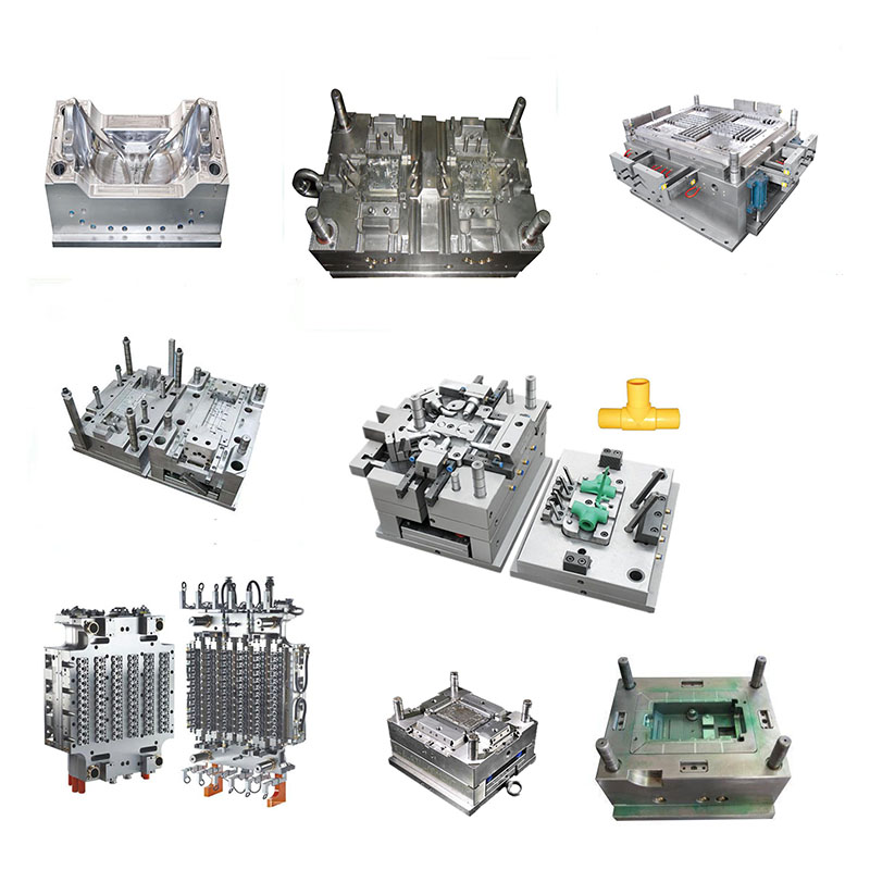
Custom Plastic Connectors moulding
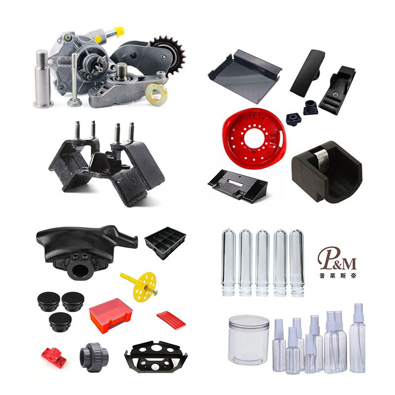
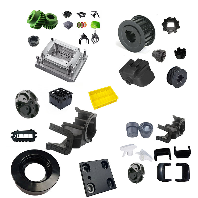
Ningbo (P&M) Plastic Metal Products Co., Ltd. has 17 years of mold manufacturing technology and can customize Custom Plastic Connectors moulding. We provide professional customized Custom Plastic Connectors moulding services, and we are a professional Custom Plastic Connectors moulding manufacturer. We have sufficient experience in selecting product raw materials and mold materials. In the process of customizing Custom Plastic Connectors moulding, our factory can provide one-stop service. We have design and production capabilities related to Custom Plastic Connectors moulding, such as: CAD design, mold manufacturing, injection molding, plastic product production, assembly and other technologies.
Send Inquiry
Product Description
In addition, our company has established cooperative relationships with plastic raw material suppliers, printing manufacturers, etc. to ensure the supply of raw materials and printing quality. Through our rich experience and perfect supply chain, our company can provide customers with high-quality customized Custom Plastic Connectors moulding products to meet their specific needs. At the same time, we have 10 years of professional foreign trade service experience, understand the foreign trade process, and better serve our customers. For Custom Plastic Connectors moulding products, we can make corresponding plastic parts, which is mainly done through injection molds.
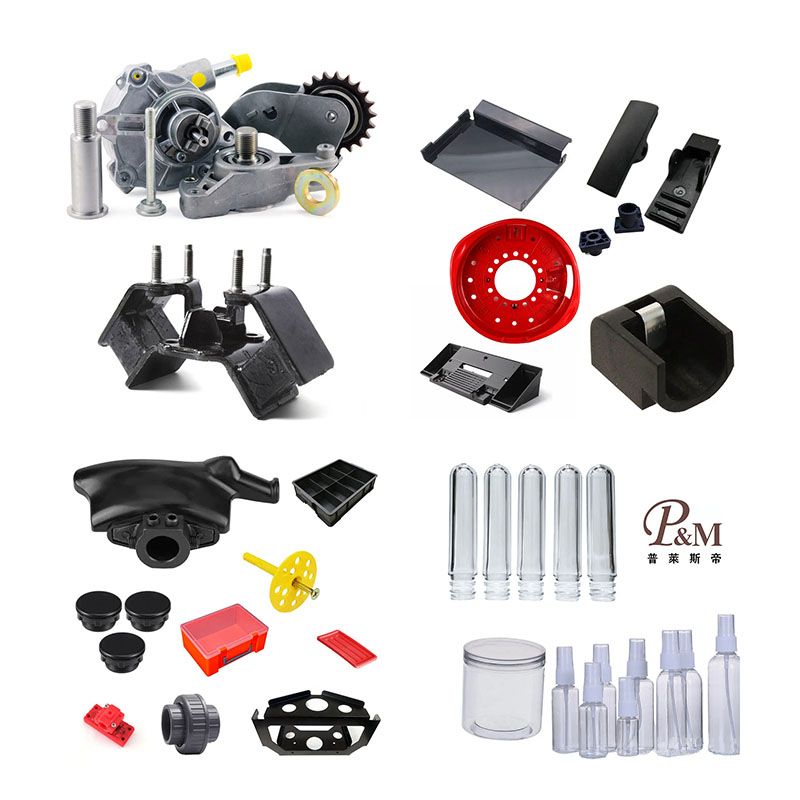
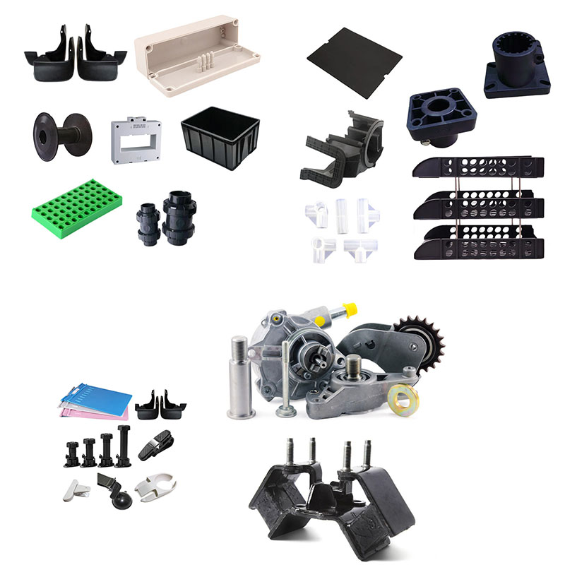
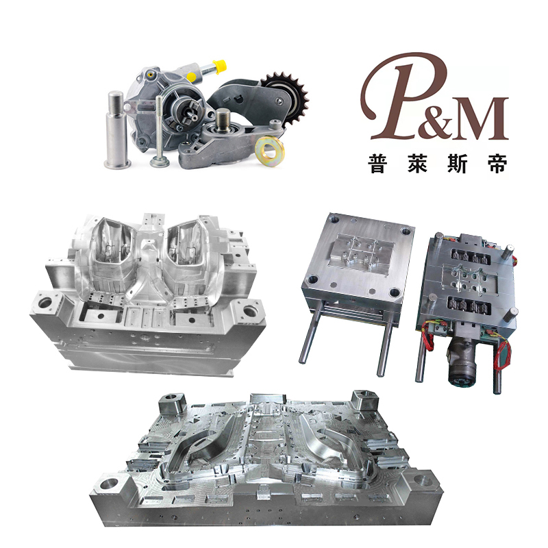
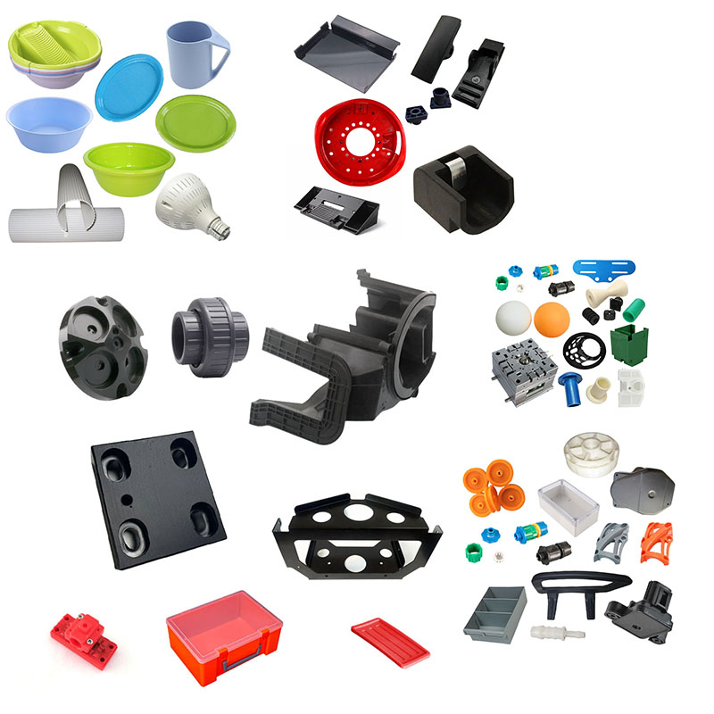
Plastic connectors are components that perform functions such as connecting, positioning, fastening, force transmission, limiting movement, and vibration damping across various products. Common forms include snap-fits, threaded bosses, pins, sleeves, brackets, butt joints, and quick-connect fittings; they are widely used inside sensors, computer mice, small home appliances, and industrial equipment. The key distinction between these and housing components is that while housings prioritize protection and aesthetics, plastic connectors focus primarily on **mechanical properties, dimensional fit precision, and long-term creep stability**, with appearance being a secondary consideration. When customizing plastic connectors, one cannot simply look at whether a 3D model is moldable; it requires comprehensive control across the entire chain—structural design, material selection, mold making, injection molding processes, dimensional tolerances, and reliability validation. The key points for customization are detailed below by module.
I. Structural DFM (Design for Manufacturability) Requirements (Crucial Before Mold Making)
The vast majority of plastic connectors are load-bearing components; design flaws can directly lead to assembly jams, breakage, loosening, or creep failure during long-term use. A DFM review must be completed before mold making begins.
1. Wall Thickness Design Principles
The recommended wall thickness for the main body of the connector is **1.2–2.5 mm**. Uniform wall thickness is preferred to avoid abrupt transitions between thick and thin sections.
- Wall thickness too thin (<1.0 mm): Insufficient strength, prone to breakage under load, difficult mold filling, and prominent weld lines.
- Wall thickness too thick (>2.8 mm): Longer cooling cycles; internal vacuum voids and sink marks occur; high material shrinkage leads to dimensional instability and increased creep risk.
- Ribs: Rib thickness should be 0.6–0.7 times the main wall thickness. Rib roots must feature R0.2–R0.3 fillets to eliminate sharp corners that cause stress concentration. Right angles at rib roots are strictly prohibited, as they are highly prone to cracking under load. Rib height generally should not exceed three times the wall thickness; excessive height can lead to trapped air and poor weld line quality. - Screw bosses: As the most common fastening elements, the recommended outer diameter is at least twice the hole diameter. Incorporate a "volcano" (recessed) feature at the base to eliminate sink marks on the outer wall, and add triangular ribs at the bottom to enhance torsional and pull-out resistance. Screw bosses should not be designed in isolation; connect them to main structural ribs whenever possible to distribute fastening stress.
2. Draft Angles and Undercut Structures
- Draft angle for non-cosmetic, load-bearing surfaces: ≥0.5°; for textured surfaces, increase the draft angle to 1.5°–3°.
- Lateral undercut structures—such as snap-fits, side holes, and side bosses—require lifters or sliders for molding. **Slider/lifter locations are high-risk zones for structural weakness**: weld lines often form at load-bearing undercut points, significantly reducing strength. Minimize the number of undercuts during the design phase; if undercuts are unavoidable, ensure weld lines do not coincide with load-bearing cross-sections.
- For plug-in connectors (quick-connects) featuring multiple internal undercuts, strictly control the clearance for lifter movement to prevent flash, as flash can directly cause jamming or sticking during insertion and removal.
3. Snap-fit Design Essentials (Most Common Plastic Fasteners)
Snap-fits function as cantilever beams and are central to elastic connections; deflection and stress must be calculated during design:
- Apply a fillet radius of R0.3–R0.5 at the snap-fit base to eliminate stress concentration caused by sharp corners.
- Wall thickness typically ranges from 0.8 mm to 1.5 mm; the ratio of effective cantilever length to wall thickness should be ≤5:1. Excessive ratios increase the risk of permanent deformation (creep), leading to loosening over time.
- Snap-fit assembly angles: Use an entry angle of 15°–30° to facilitate assembly. The locking angle for the undercut is generally 70°–90°; a larger angle provides stronger retention but also causes a sharp increase in the force required for disassembly.
- In multi-snap designs, ensure even load distribution to avoid localized stress overload. For snap-fits subject to repeated assembly and disassembly, reduce the maximum bending stress to prevent breakage. ### 4. Fit Tolerances and Locating Structures
Plastic connectors are mating parts; dimensional tolerances cannot simply copy housing standards—fit classes must be distinguished:
- Clearance fit (sliding pins, plug-in parts): Tolerance ±0.03 to ±0.08 mm;
- Transition/interference fit (locating posts, mating spigots): ±0.02 to ±0.05 mm;
- Non-mating installation dimensions: ±0.10 mm;
>
> Important: Plastics exhibit shrinkage, and rates vary significantly by material. Drawings must specify the material-specific shrinkage rate so that mold machining can account for it. Glass fiber-reinforced materials exhibit anisotropic shrinkage (rates differ between parallel and perpendicular directions to the fibers), making them prone to ovality and deformation; design compensation allowances accordingly.
- Locating: For long-distance mating connectors, designs must incorporate both primary and auxiliary locating features to prevent assembly misalignment and avoid eccentric stress during fastening.
5. Stress-Avoidance Design
All load-bearing corners must be radiused; sharp right angles are prohibited. Load-bearing cross-sections should feature smooth transitions to avoid abrupt changes in geometry. Avoid placing small holes in load-bearing areas, as they create stress concentration points where fractures can occur under load.
II. Material Selection and Customization Requirements (Determined by load, environment, and service life)
Material choice is the foundation of connector reliability; selection should not be based solely on cost. Key evaluation criteria include: tensile strength, flexural modulus, creep resistance, temperature resistance, chemical resistance, and fatigue resistance.
1. **ABS**: Low cost, decent toughness, good moldability; suitable for low-load, indoor, room-temperature, one-time assembly connectors. Poor creep resistance—prone to loosening under long-term stress—making it unsuitable for structures requiring permanent fastening under load; poor solvent resistance.
2. **PC/ABS**: Excellent overall toughness and superior impact resistance compared to ABS; suitable for medium-load applications, such as internal mounting brackets in consumer electronics. Moderate creep resistance; unsuitable for structures subjected to continuous, constant pressure. 3. **PC (Polycarbonate)**: High strength, impact resistance, and a wide operating temperature range; suitable for parts subject to high impact loads. Disadvantages: Sensitive to residual stress; prone to cracking under fastening or assembly stress; high moisture absorption.
4. **POM (Polyoxymethylene/Acetal)**: **One of the preferred materials for plastic connectors**; low coefficient of friction, dimensional stability, excellent creep resistance, good elasticity, and wear resistance. Suitable for snap-fits, pins, sliding joints, and quick-connect/disconnect parts. Note: POM cannot be electroplated, has poor flame retardancy, and is prone to flow marks (gas streaks) during molding.
5. **PA6/PA66 Nylon (Glass-fiber reinforced)**: Glass-fiber reinforced PA offers extremely high strength and rigidity, as well as temperature and oil resistance; suitable for industrial high-load brackets. Disadvantages: Nylon absorbs water, leading to changes in dimensions and strength; humidity conditions must be evaluated.
6. **PBT (Glass-fiber reinforced)**: Excellent dimensional stability, low creep, and resistance to chemicals and heat; commonly used for industrial control sensors and internal load-bearing connectors. Surface is prone to "fiber blooming" (exposed glass fibers).
7. **PP**: Good toughness, hydrolysis resistance, and low cost; poor rigidity and high creep; suitable only for light-load connection structures.
8. **TPU/TPE**: Soft connectors used for shock absorption, sealing, and elastic cushioning joints; often used in two-shot (dual-material) molding with rigid plastics.
>
> Key selection criteria:
> ① Continuous loading (constant compression, long-term fastening) → Prioritize POM or glass-fiber reinforced PBT for creep resistance;
> ② Repeated insertion/removal or frequent disassembly/assembly → Prioritize POM;
> ③ High/low temperatures, outdoor use, or chemical exposure → Glass-fiber reinforced PBT or PA;
> ④ Flame retardancy requirements → Select materials with UL94-V0 ratings.
## III. Key Points for Mold Customization
For plastic connector molds, priority is given to **dimensional stability, weld line strength, and minimizing flash**; aesthetic appearance is a lower priority. 1. **Gate Design**
Gate placement is the most critical design aspect for connector molds: **gates should avoid load-bearing cross-sections whenever possible, and weld lines must strictly avoid areas subject to primary stress.**
- Load-bearing brackets and snap-fits: Prioritize side gates or fan gates to minimize shear stress; avoid using tiny pin-point gates.
- POM materials: Gate cross-sections must not be too small; excessive shear causes POM to overheat and decompose, releasing gas that leads to gas marks and embrittlement.
- Multi-cavity molds: Runner systems must be balanced to ensure consistent filling across cavities, preventing variations in part strength and dimensions.
Venting System**
Venting channels must be incorporated at locations such as ribs, snap-fits, sliders, and weld lines. Inadequate venting at weld lines significantly reduces weld strength—sometimes to less than 30% of the base material's strength—causing parts to fracture under load.
POM melt decomposition releases formaldehyde gas; poor venting easily leads to scorching and embrittlement. For glass-fiber reinforced materials, vent depth should be 0.02–0.03 mm.
3. **Cooling System**
Connectors require high dimensional stability; cooling channels should be positioned close to the cavity to ensure uniform mold temperature and minimize part deformation and warpage. Glass-fiber reinforced parts exhibit significant anisotropic shrinkage; uneven cooling causes twisting and assembly interference. Molds should be equipped with temperature control units for zoned temperature regulation.
4. **Mold Steel**
Standard ABS, PC/ABS: 718H, NAK80; Glass-fiber reinforced materials, POM: S136, SKD61. Glass fibers cause abrasive wear on mold cavities; insufficient hardness leads to rapid wear, resulting in dimensional drift and increased flash. Materials for sliders and lifters must be wear-resistant, and fitting clearances must be strictly controlled to prevent flash.
We are a Custom Plastic Connectors moulding manufacturer, providing high-quality Custom Plastic Connectors moulding manufacturing. As long as you want to customize/develop Custom Plastic Connectors moulding products, you can find us. We have professional injection mold design and mature manufacturing technology, providing you with one-stop service, from product design-mold making-product production-product packaging-product transportation, we can help you in every link. As long as you come to us, we will provide you with the ultimate service and satisfy you in terms of product quality, production time, information dialogue, etc.
|
Product Name |
Treadmill moulding |
|
Pls provide |
2D, 3D, samples, or the size of the multi-angle pictures |
|
Mould Time |
20-35 Days |
|
Product time |
7-15 Days |
|
Mould precision |
+/-0.01mm |
|
Mould life |
50-100 million shots |
|
Producing Process |
Audit drawings - mold flow analysis - design validation - Custom Materials - mold processing - core processing - electrode machining - Runner system processing - parts processing and procurement - machining acceptance - cavity surface treatment process - complex mode Die - The entire mold surface coating - Mounting plate - mold sample - sample test - sending samples |
|
Mould cavity |
One cavity, multi-cavity or same different products be made together |
|
Mould material |
P20,2738,2344,718,S136,8407,NAK80,SKD61,H13 |
|
Runner system |
Hot runner and cold runner |
|
Base material |
P20,2738,2344,718,S136,8407,NAK80,SKD61,H13 |
|
Finish |
Pitting the word, mirror finish, matte surface, striae |
|
Standard |
HASCO, DME or dependent upon |
|
Main technology |
Milling, grinding, CNC, EDM, wire cutting, carving, EDM, lathes, surface Finish, etc. |
|
Software |
CAD,PRO-E,UG Design Time: 1-3 days (normal circumstances) |
|
Product material |
ABS,PP,PC,PA6,PA66,TPU,POM,PBT,PVC,HIPS,PMMA,TPE,PC/ABS,TPV,TPO,TPR,EVA,HDPE,LDPE,CPVC,PVDF,PPSU.PPS. |
|
Quality system |
ISO9001:2008 |
|
Establish time |
20days |
|
Equipment |
CNC,EDM,Cutting off Machine,plastic machinery,etc plastic suitcase mould zhe jiang |
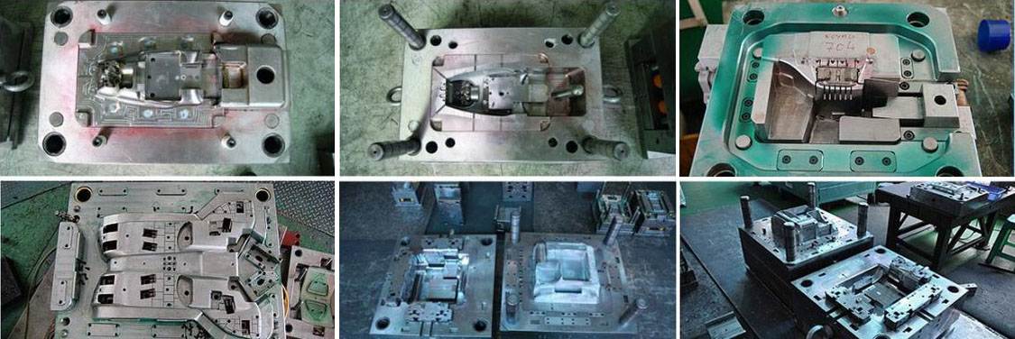
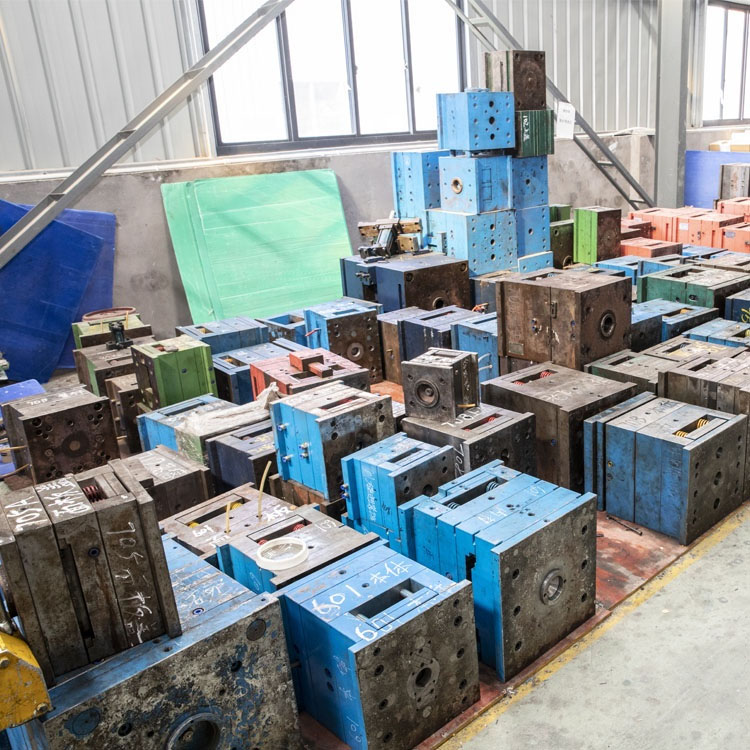
Plastic Injection Mould making
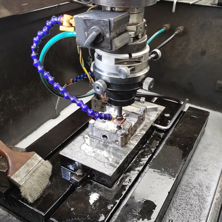
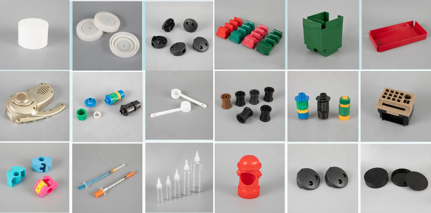
Plastic molding specifications
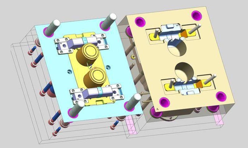
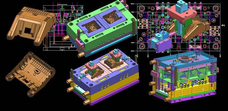
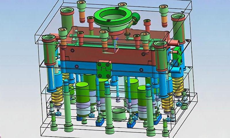
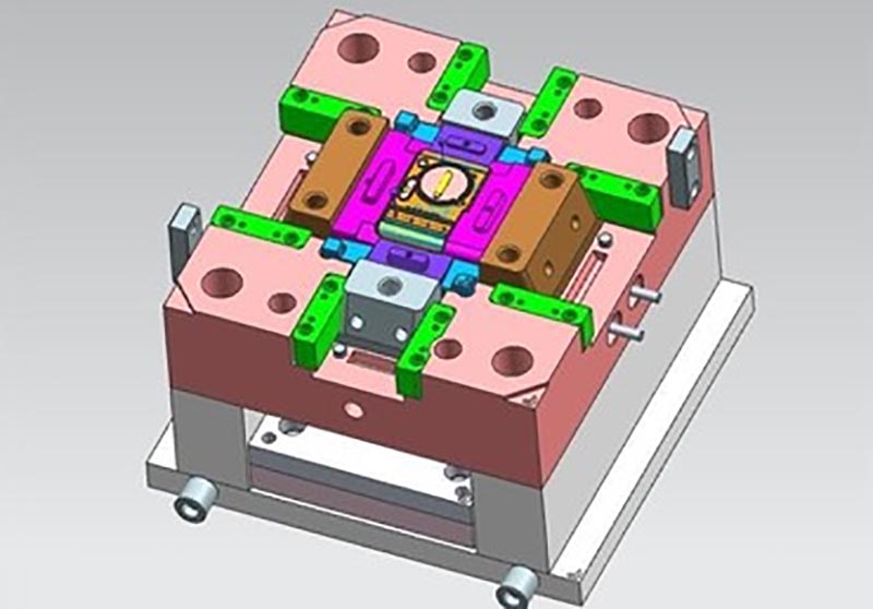
Mold design:
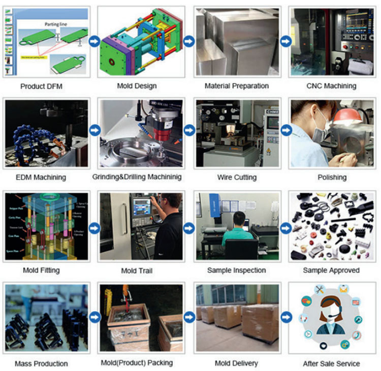
Transaction process:
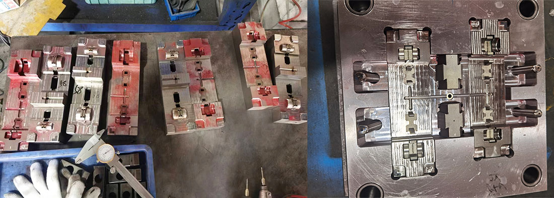
Mold testing:

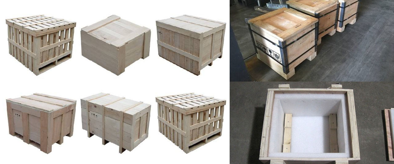
Product packaging
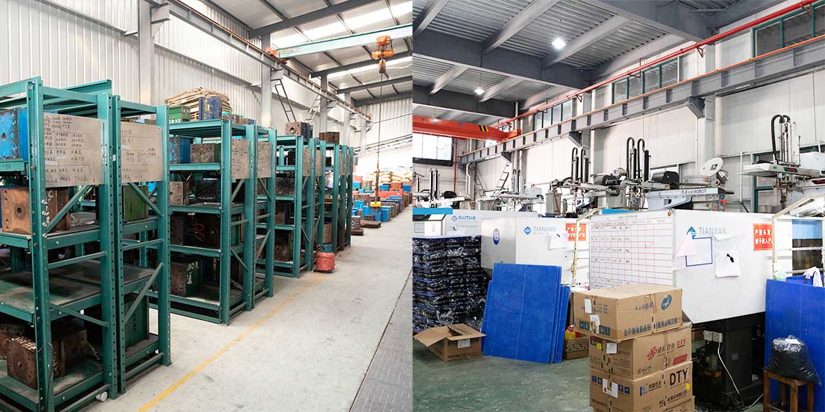
Factory
We are Custom Plastic Mold factory. Our factory is plastic injection mold maker. we has 17 years of experience in professional custom plastic mold and 10 years of foreign trade experience. We are custom Plastic Mold supplier. We can provide custom Plastic Mold service. Our factory can make the Injection molded plastic parts, and the quality of the products will satisfy you.
We have more than 50 high-end machines and hundreds of engineers and designers. We can provide one-stop service, from product design - mold making - product production - product packaging - transportation. We have a complete production chain. We can meet all your requirements.
Services we provide:
Professional custom mold service, Plastic mold design and manufacturing .plastic product production, product design, mold design, blow mold customization, rotational mold customization, die-casting mold customization. 3D printing services, CNC manufacturing services, product packaging, customized packaging, shipping services.
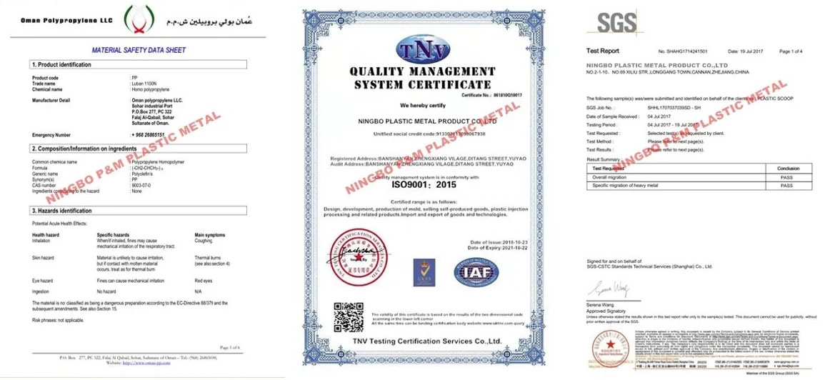

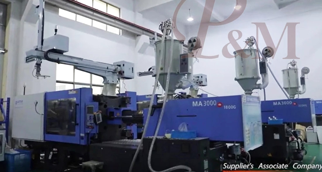
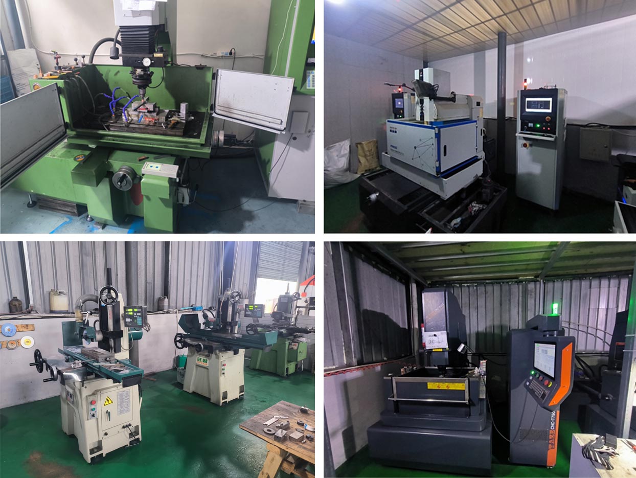
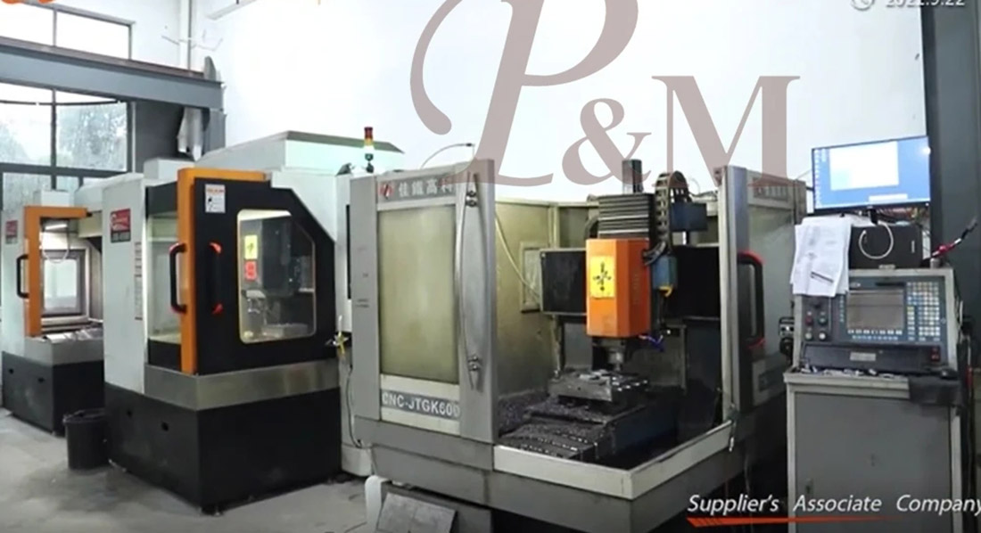
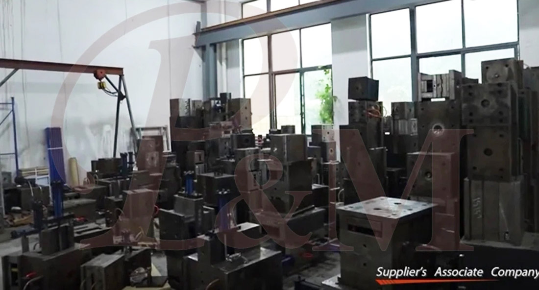
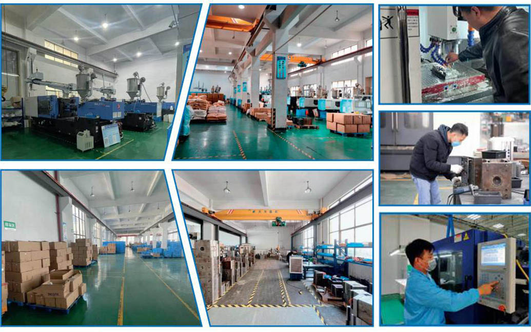

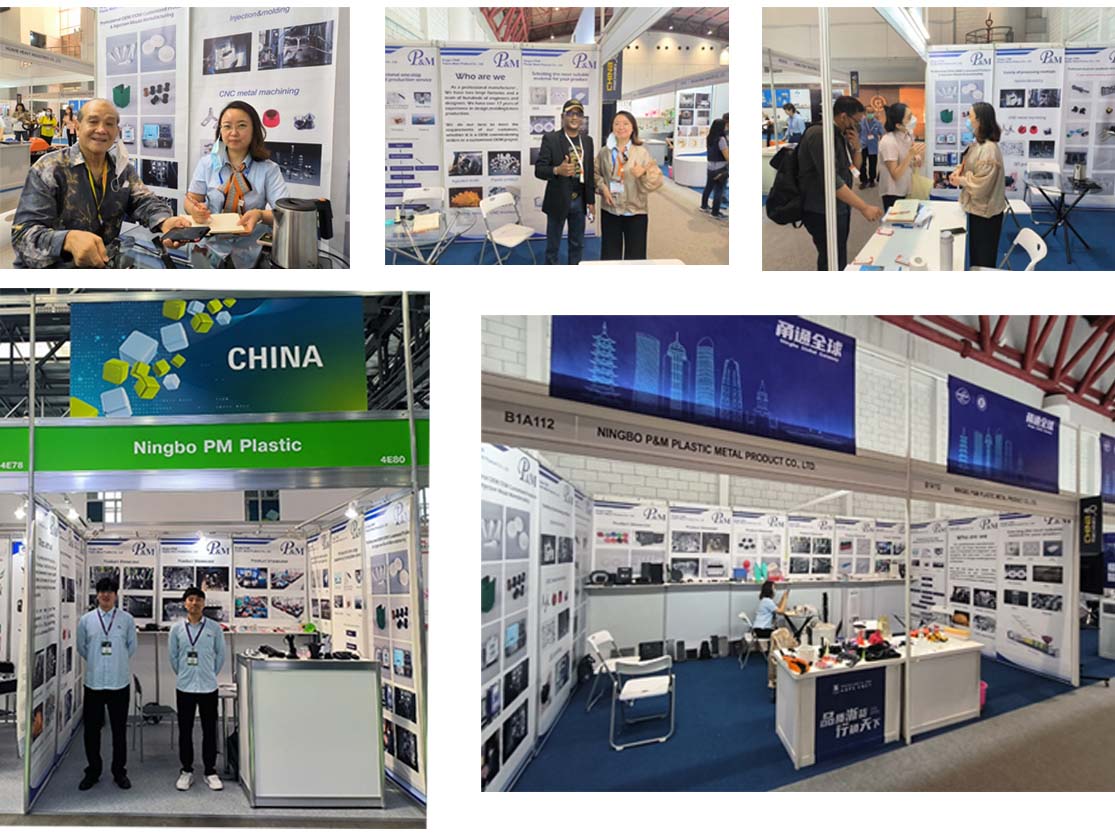
We always adhere to the principles of quality first and time first. While providing customers with the highest quality products, try to maximize the production efficiency and shorten production time. We are proud to tell every customer that our company has not lost any customer since its establishment.If there is a problem with the product, we will seek a solution actively and take responsibility to the end.

FAQ
Q1: Are you trading company or manufacturer ?
A: We are manufacturers.
Q2. When can I get the quotation?
A: We usually quote within 2 days after we get your inquiry.
If you are very urgent, please call us or tell us in your email so that we can quote for you first.
Q3. How long is the lead-time for mold?
A: It all depends on the products' size and complexity. Normally, the lead time is 25 days.
Q4. I have no 3D drawing, how should I start the new project?
A: You can supply us a molding sample, we will help you finish the 3D drawing design.
Q5. Before shipment, how to make sure the products quality?
A: If you don't come to our factory and also don't have the third party for inspection, we will be as your inspection worker.
We will supply you a video for production process detail include process report, products size structure and surface detail, packing detail and so on.
Q6. What is your payment terms?
A: Mold Payment: 40% deposit by T/T in advance, 30% second mold payment before sending out the first trial samples, 30% mold balance after you agree the final samples.
B:Production Payment: 50% deposit in advance, 50% before sending out the final goods.
Q7: How do you make our business long-term and good relationship?
A:1. We keep good quality and competitive price to ensure our customers benefit for best quality products.
2. We respect every customer as our friend and we sincerely do business and make friends with them, no matter where they come from.
Hot Tags: Custom Plastic Connectors moulding, China, Manufacturer, Supplier, Factory, Customized, Wholesale, Buy, Quality, Latest Selling, Made in China
Related Category
Send Inquiry
Please feel free to give your inquiry in the form below. We will reply you in 24 hours.