
Home
>
Product > Core Customization Service > Custom Molding > Customization of Button Device Parts moulding
Product
- Core Customization Service
- Health Care
- Electronic Appliances and Instruments
- Maternal and Child Supplies Molds
- Recreational Sports
- Home Furnishing Art
- Auto Accessories
- Transportation and Warehousing
- Lighting Fixtures
- Construction Equipment
- Packaging Product
- Educational & Laboratories
- Clothing Luggage Accessories
- Care and Cleaning Products
- Agriculture & Forestry
- Mechanical Equipment
- Pet Supplies
- Kitchenware

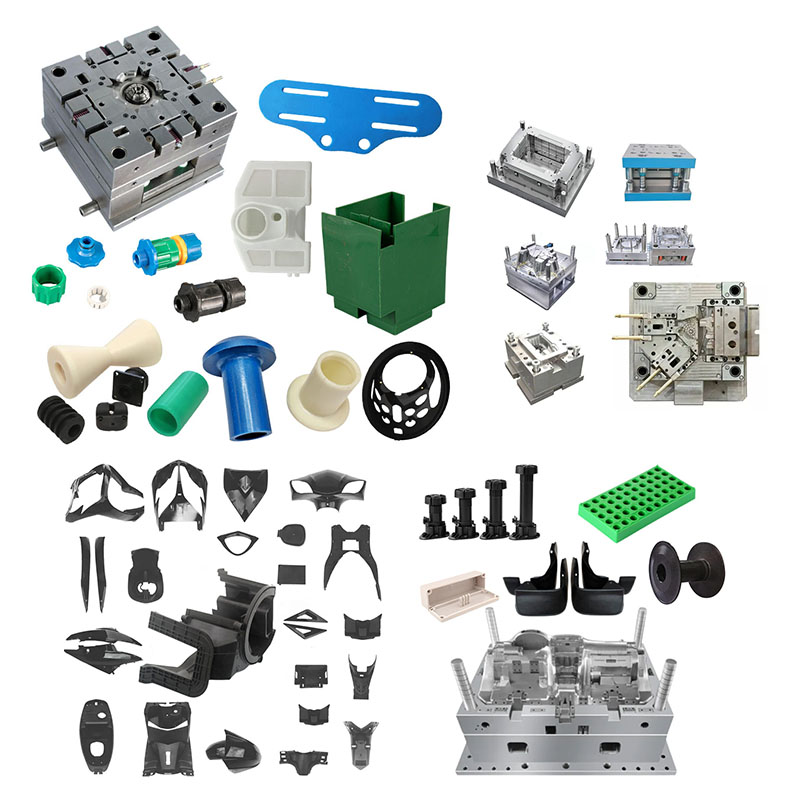
Customization of Button Device Parts moulding
Ningbo (P&M) Plastic Metal Products Co., Ltd. has 17 years of mold manufacturing technology and can customize Customization of Button Device Parts moulding. We provide professional customized Customization of Button Device Parts moulding services, and we are a professional Customization of Button Device Parts moulding manufacturer. We have sufficient experience in selecting product raw materials and mold materials. In the process of customizing Customization of Button Device Parts moulding, our factory can provide one-stop service. We have design and production capabilities related to Customization of Button Device Parts moulding, such as: CAD design, mold manufacturing, injection molding, plastic product production, assembly and other technologies.
Send Inquiry
Product Description
In addition, our company has established cooperative relationships with plastic raw material suppliers, printing manufacturers, etc. to ensure the supply of raw materials and printing quality. Through our rich experience and perfect supply chain, our company can provide customers with high-quality customized Customization of Button Device Parts moulding products to meet their specific needs. At the same time, we have 10 years of professional foreign trade service experience, understand the foreign trade process, and better serve our customers. For Customization of Button Device Parts moulding products, we can make corresponding plastic parts, which is mainly done through injection molds.
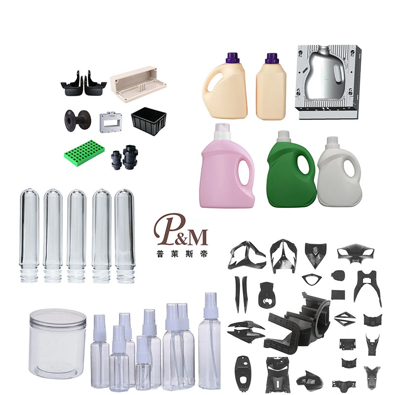
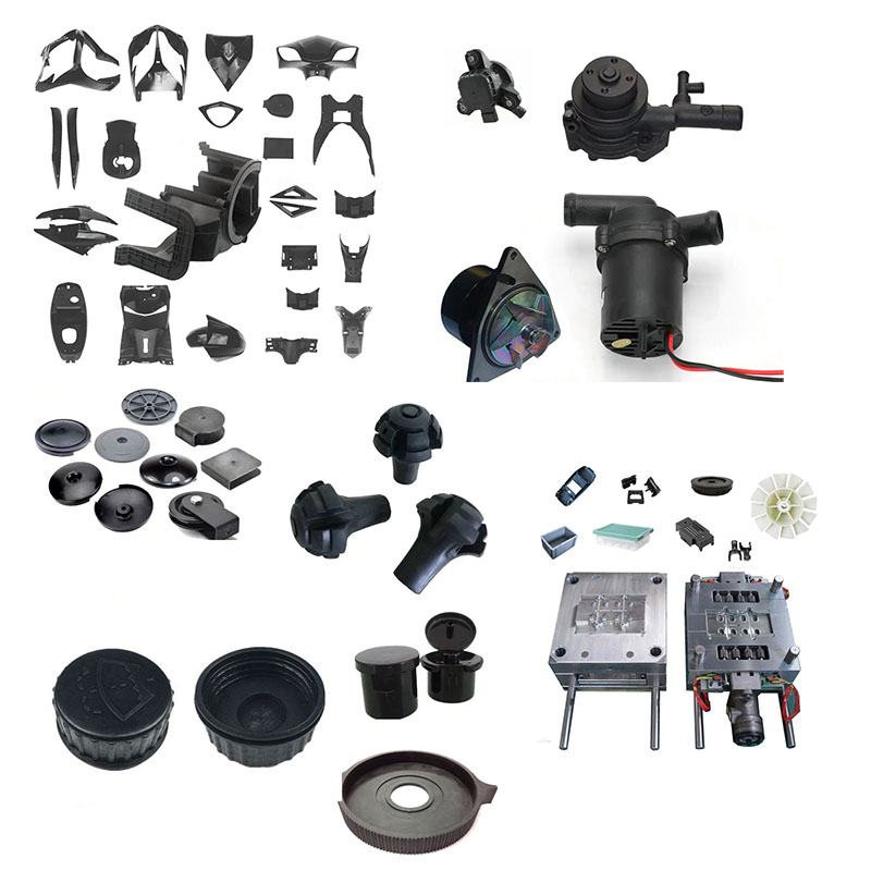
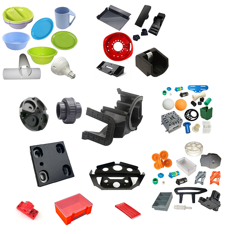
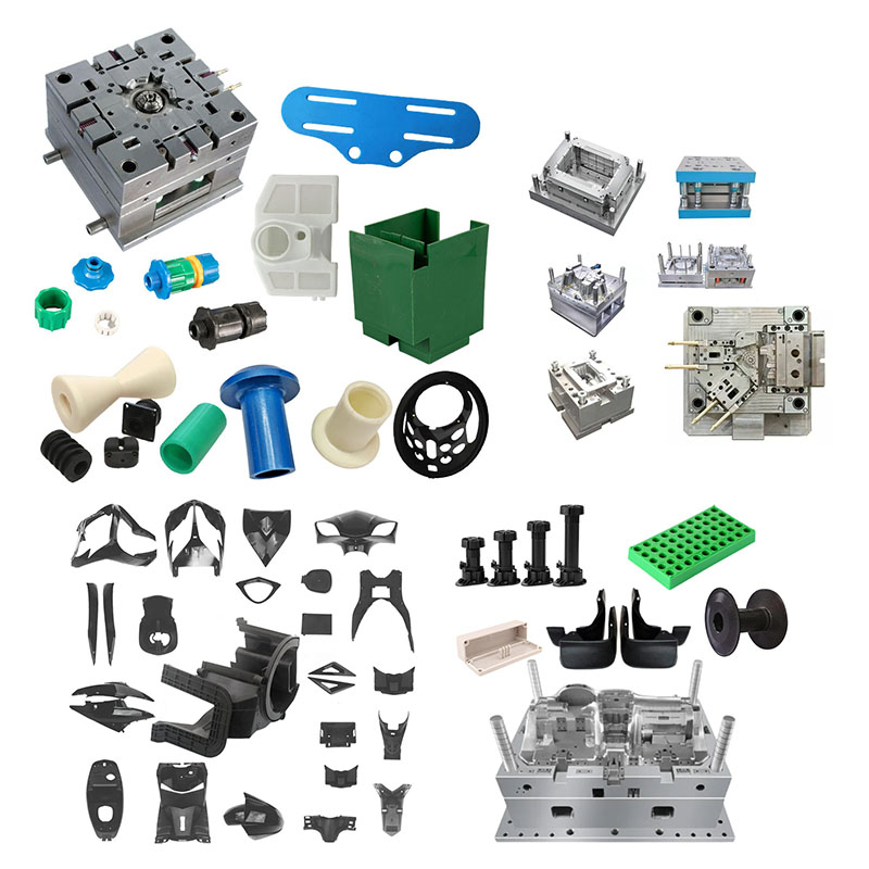
Button components are classified as **human-machine interface (HMI) functional parts** and are widely used in products such as sensors, home appliances, instruments, industrial control equipment, computer mice, and electric shavers. They generally consist of the following elements: button caps (outer caps), key brackets, push rods, silicone key bases, travel limiters, and return/support structures. Unlike standard housings or structural connectors, the core performance metrics for button components are **tactile feel, travel distance, actuation force, return consistency, fatigue resistance, and dimensional fit precision**; visual appearance is a secondary consideration (except for exposed buttons). Common pitfalls in custom button component development include drawings that specify only the external shape without defining force values or travel distances; this often leads to issues during mass production, such as a feel that is too stiff or too soft, sticking keys, sluggish return, or breakage after a million cycles. The following section details the customization requirements, covering DFM structural review, material selection, mold design, injection molding processes, dimensional tolerances, assembly verification, and reliability testing.
I. Preliminary DFM Structural Design Review (Critical Step Before Mold Making)
The primary objective in button component design is to ensure **smooth sliding, freedom from sticking, stable return action, and minimal stress concentration**. A DFM (Design for Manufacturability) review must be completed before mold making, with a focus on wall thickness, draft angles, guiding mechanisms, travel limits, and return structures.
1. Wall Thickness Design
The recommended wall thickness for the button body is 1.2–2.0 mm. Uniform wall thickness is the foundation for consistent tactile feel; abrupt changes in thickness can lead to uneven shrinkage and warping, directly causing the button to stick.
- Thin walls (<1.0 mm): Insufficient rigidity; prone to tilting or deformation during pressing.
- Thick walls (>2.2 mm): High shrinkage; prone to sink marks, deformation, and dimensional instability.
- Ribs: Rib thickness should be 0.6–0.7 times the main wall thickness; rib roots require a fillet radius of R0.2–R0.3 (sharp right angles are prohibited). Ribs are primarily used to enhance overall rigidity and should not be placed on sliding friction surfaces. - Cantilever return rib (plastic self-returning button; no silicone used): Cantilever wall thickness is 0.8–1.2 mm; a large fillet radius (R0.3–R0.5) is applied at the cantilever root to eliminate stress concentration; the cantilever's aspect ratio is strictly controlled to prevent fatigue fracture.
2. Draft Angles and Guiding Structures
Buttons typically function as components that slide vertically; therefore, guiding ribs are of critical importance.
- Draft angle for sliding guide surfaces: **0.3°–0.8°**. It must not be excessive; otherwise, the clearance varies with height, causing the button to tilt or wobble during pressing. If the draft is too small, the part may suffer surface damage (scuffing) during demolding, and sliding resistance increases. For exposed "Class A" button surfaces, the draft angle should be ≥1° (or ≥2° if a textured finish is applied).
- Guiding rib design: Typically, 2–4 symmetrical guiding ribs are used to ensure vertical movement and prevent lateral tilting or jamming. Rib width is 1.0–1.5 mm, and the guiding fit clearance is controlled at 0.03–0.08 mm. Insufficient clearance leads to jamming due to thermal expansion, while excessive clearance causes the button to shake or sway laterally.
- Undercut structures: Snap-fits or stop-undercuts on the button sides require lifters or sliders for molding. **Slider locations should avoid guide surfaces whenever possible**, as flash generated by the slider can directly cause the button to jam.
3. Travel, Limit, and Stop Structures (Must be defined during customization)
For custom buttons, the following specifications must be clearly marked on the drawing: **total travel, effective working travel, pre-load travel, and stop clearance**. - Total travel: The total displacement of the button from its highest point to the bottom;
- Effective travel: The displacement required to actuate the switch;
- Limit ribs / stop bosses: Designed as hard stops to prevent over-pressing, protecting the internal microswitch from damage and the plastic cantilever from fatigue failure due to excessive bending (over-travel);
- Rebound clearance: A gap left in the stop mechanism after the button resets to prevent creep caused by prolonged compression, which could otherwise lead to the button sinking or failing to return to its original position.
4. Mating tolerance requirements
Buttons are moving mating parts; tolerance requirements are stricter than those for standard housings and are defined by zone:
- Guiding sliding mating surfaces: ±0.02 to ±0.05 mm;
- Push-rod end face (contacting the PCB microswitch) and locating posts: ±0.03 to ±0.06 mm;
- Non-mating cosmetic / mounting dimensions: ±0.10 mm;
>
> Glass fiber-reinforced materials exhibit anisotropic shrinkage; compensation must be factored into the design to prevent elliptical deformation of guide ribs, which could cause the button to jam.
> Material shrinkage rates must be specified on the drawing so that mold machining accounts for this shrinkage.
5. Contact structure design
The push-rod head (where it contacts the microswitch) should ideally feature a small radius (R0.3–R0.5) to avoid pressing the switch with a sharp point, which could scratch the switch contacts during repeated use. For self-returning plastic cantilever buttons, the force applied to the cantilever should be unidirectional to avoid torsional stress; torsion significantly reduces fatigue life.
II. Key points for material selection and customization
Key factors for button material selection include: **coefficient of friction, fatigue resistance, rebound stability, creep resistance, and temperature resistance**. Two categories of solutions exist: ① All-plastic rigid buttons (self-returning, no silicone); ② Plastic button cap with a silicone gasket for the return mechanism.
1. **ABS**: Low cost and good moldability; suitable for light-duty, low-cycle, indoor general-purpose buttons. Disadvantages: Average fatigue resistance; prone to creep and sinking under prolonged compression; relatively high coefficient of friction, resulting in high sliding resistance. 2. **PC/ABS**: Good toughness and impact resistance; commonly used for exposed buttons. Offers better fatigue resistance than ABS, though it is prone to creep under sustained long-term stress.
3. **PC**: High rigidity and heat resistance; however, it is sensitive to internal stress, prone to generating noise during sliding friction, and has mediocre fatigue resistance regarding repeated bending, making it unsuitable for plastic cantilevered self-returning buttons.
4. **POM (Polyoxymethylene; the top choice for buttons)**: Low coefficient of friction, self-lubricating, dimensionally stable, and excellent at resisting creep and fatigue. Ideal for sliding guide structures, push rods, and self-returning cantilever buttons; resists sagging or jamming even after a million presses. Disadvantages: Poor flame retardancy; cannot be electroplated.
5. **Glass-fiber reinforced PBT**: High rigidity, low creep, and good heat/chemical resistance; used for industrial control equipment buttons. Disadvantages: Surface fiber exposure (floating fibers); fibers on friction surfaces increase sliding resistance, requiring strict molding control.
6. **Glass-fiber reinforced PA6/PA66**: High strength and heat resistance; used for heavy-duty industrial buttons. Water absorption alters dimensions, and humidity fluctuations affect tactile feel; environmental conditions must be evaluated.
7. **TPU/TPE**: Soft materials used for dual-material overmolding to create non-slip button surfaces or cushioning pads; also used for soft-rebound structures.
>
> Selection Criteria:
> ① Requires a million+ presses, consistent feel, and smooth sliding → **POM (Preferred)**
> ② Exposed buttons requiring painting or UV coating → PC/ABS
> ③ Industrial control equipment in high-temperature or chemical environments → Glass-fiber PBT
> ④ Low budget, infrequent pressing → ABS
Key Points for Mold Customization
Primary objectives for button molds: **Ensure no flash on sliding surfaces, maintain dimensional stability, and position weld lines away from guiding or load-bearing areas.**
1. **Gate Design**
Gate locations must not be placed on sliding guide surfaces or load-bearing cantilever areas. Weld lines must strictly be avoided on guide ribs and return cantilevers; weld lines significantly reduce fatigue life, potentially leading to breakage after only a few thousand presses. - POM buttons: Side gates are preferred; gate cross-sections must not be too small. POM is prone to decomposition and gas generation due to shear-induced overheating, which causes gas marks and embrittlement.
- Small button caps: Submarine (tunnel) gates may be used, with the gate located on the non-visible bottom surface.
- Multi-cavity molds: Runner systems must be balanced, and parts from each cavity must be identical in size and weight to ensure consistent tactile feel across all buttons.
2. **Venting System**
Include vent channels at rib locations, flow ends, and slider areas. POM melt generates gas upon thermal decomposition; poor venting leads to burning and part embrittlement. Trapped air at guide rib locations causes burn marks and burrs, directly leading to button jamming.
Vent channel depth: ABS 0.02mm; PC/ABS 0.015mm; POM 0.02mm; glass-fiber reinforced materials 0.02–0.03mm.
3. **Cooling System**
Button guide structures require high dimensional precision; cooling channels should be positioned close to the cavity to ensure uniform mold temperature and minimize warpage. Independent temperature control for the upper and lower mold halves prevents uneven shrinkage of guide ribs, which could otherwise cause the button to jam on one side.
4. **Mold Steel and Fit**
ABS, PC/ABS: 718H, NAK80; POM, glass-fiber reinforced materials: S136 hardened steel. Use wear-resistant steel for sliders and lifters, and strictly control fit clearances; **no flash is permitted on sliding surfaces**, as flash is the most common mold-related cause of button jamming. Polish sliding surfaces within the cavity to reduce frictional resistance.
We are a Customization of Button Device Parts moulding manufacturer, providing high-quality Customization of Button Device Parts moulding manufacturing. As long as you want to customize/develop Customization of Button Device Parts moulding products, you can find us. We have professional injection mold design and mature manufacturing technology, providing you with one-stop service, from product design-mold making-product production-product packaging-product transportation, we can help you in every link. As long as you come to us, we will provide you with the ultimate service and satisfy you in terms of product quality, production time, information dialogue, etc.
|
Product Name |
Treadmill moulding |
|
Pls provide |
2D, 3D, samples, or the size of the multi-angle pictures |
|
Mould Time |
20-35 Days |
|
Product time |
7-15 Days |
|
Mould precision |
+/-0.01mm |
|
Mould life |
50-100 million shots |
|
Producing Process |
Audit drawings - mold flow analysis - design validation - Custom Materials - mold processing - core processing - electrode machining - Runner system processing - parts processing and procurement - machining acceptance - cavity surface treatment process - complex mode Die - The entire mold surface coating - Mounting plate - mold sample - sample test - sending samples |
|
Mould cavity |
One cavity, multi-cavity or same different products be made together |
|
Mould material |
P20,2738,2344,718,S136,8407,NAK80,SKD61,H13 |
|
Runner system |
Hot runner and cold runner |
|
Base material |
P20,2738,2344,718,S136,8407,NAK80,SKD61,H13 |
|
Finish |
Pitting the word, mirror finish, matte surface, striae |
|
Standard |
HASCO, DME or dependent upon |
|
Main technology |
Milling, grinding, CNC, EDM, wire cutting, carving, EDM, lathes, surface Finish, etc. |
|
Software |
CAD,PRO-E,UG Design Time: 1-3 days (normal circumstances) |
|
Product material |
ABS,PP,PC,PA6,PA66,TPU,POM,PBT,PVC,HIPS,PMMA,TPE,PC/ABS,TPV,TPO,TPR,EVA,HDPE,LDPE,CPVC,PVDF,PPSU.PPS. |
|
Quality system |
ISO9001:2008 |
|
Establish time |
20days |
|
Equipment |
CNC,EDM,Cutting off Machine,plastic machinery,etc plastic suitcase mould zhe jiang |
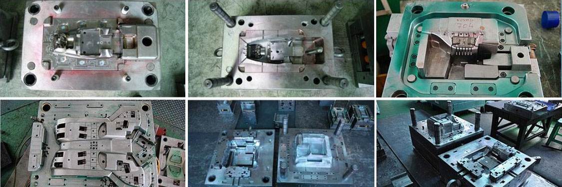
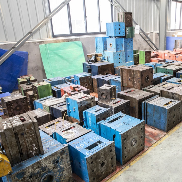
Plastic Injection Mould making
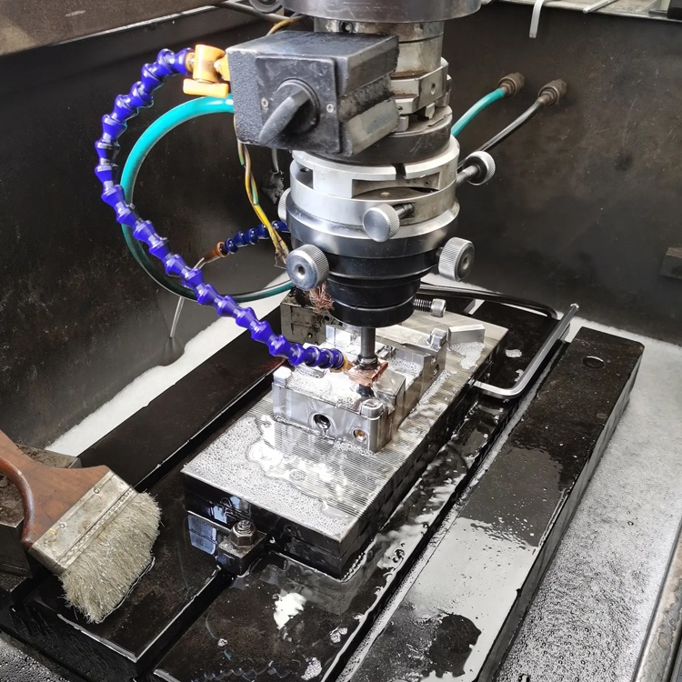
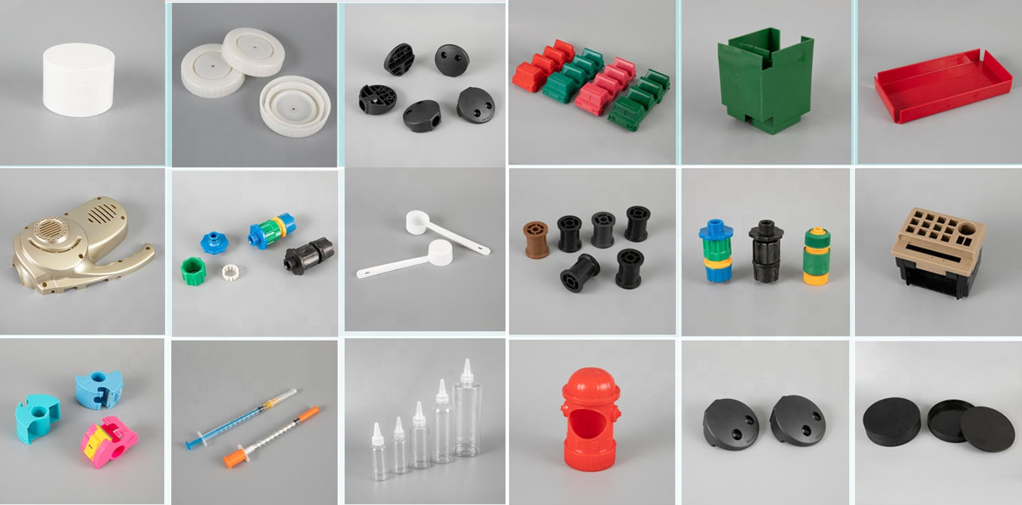
Plastic molding specifications
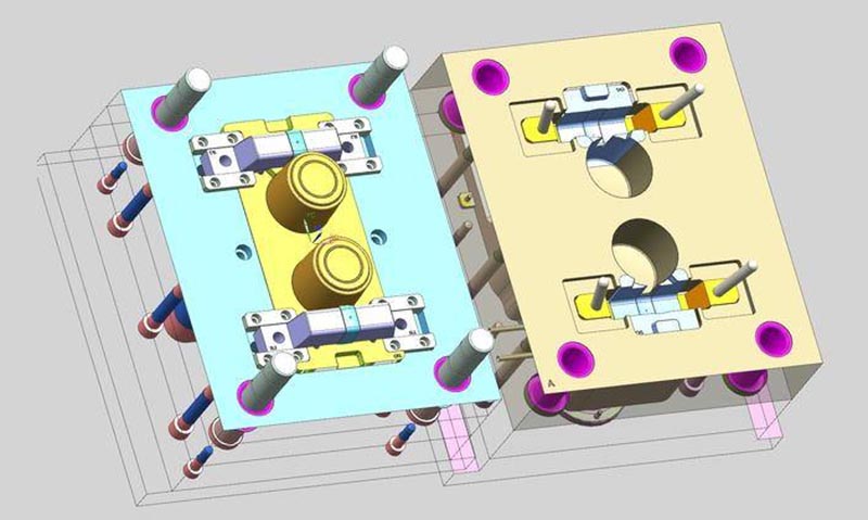
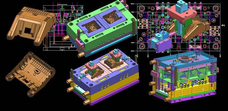
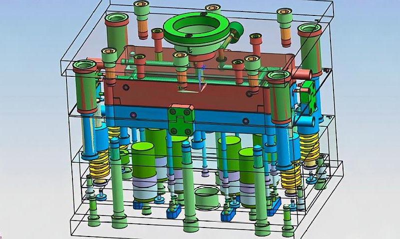
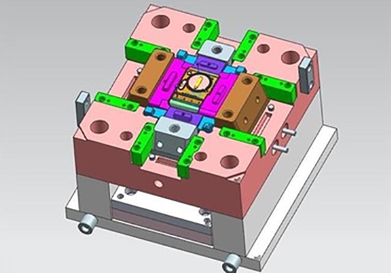
Mold design:
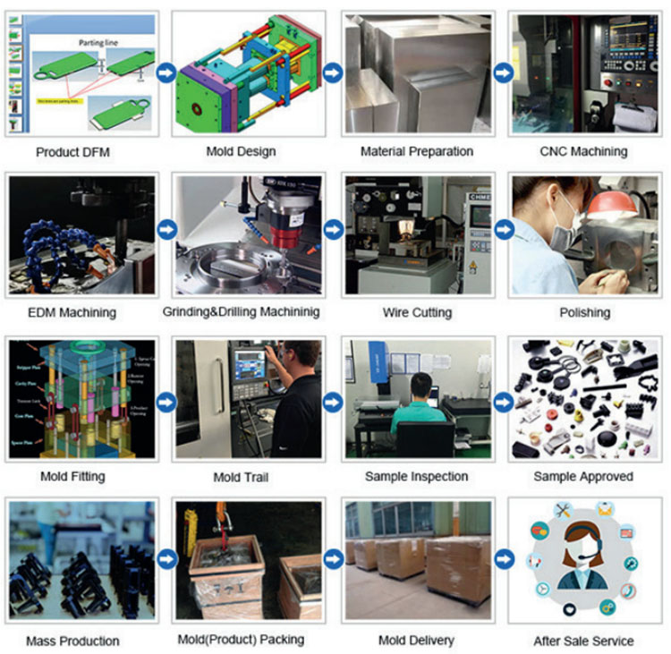
Transaction process:
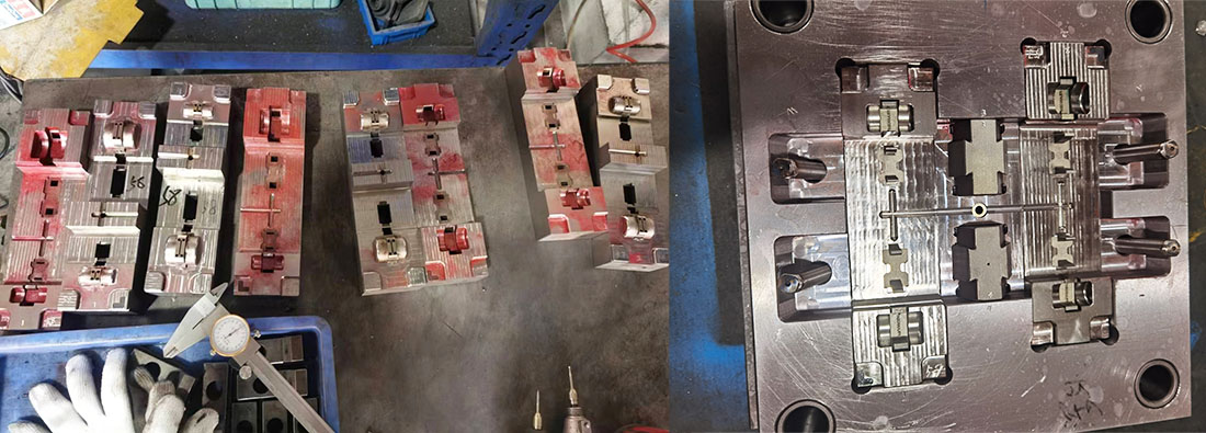
Mold testing:

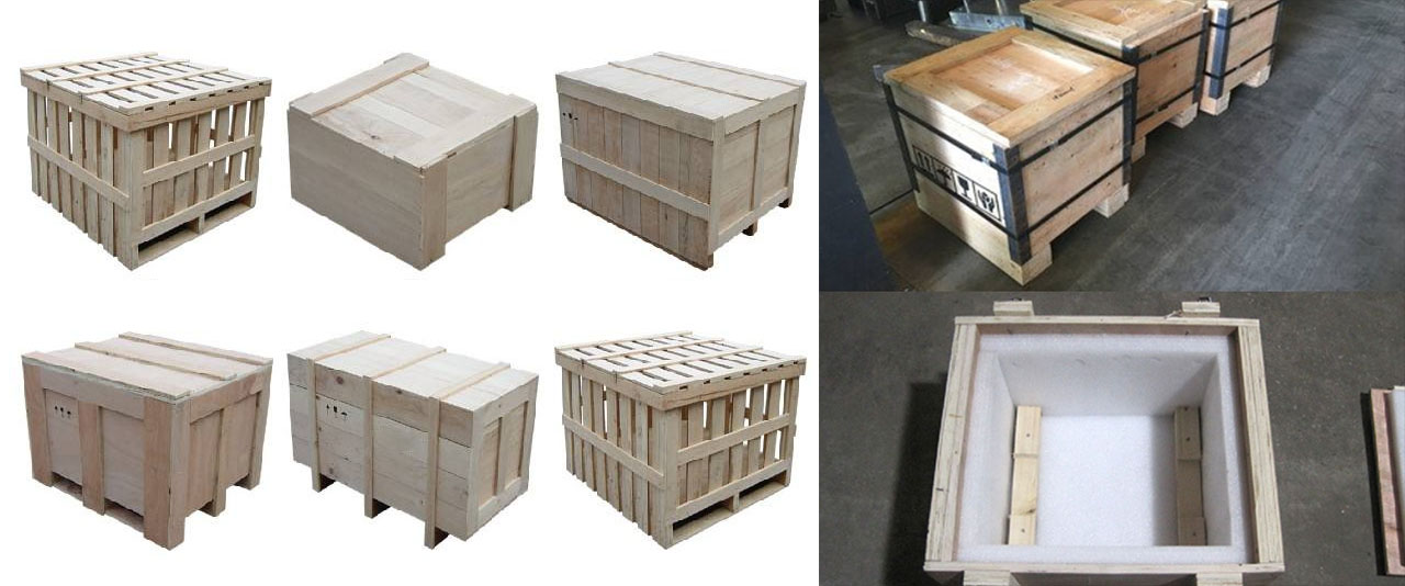
Product packaging
Factory
We are Custom Plastic Mold factory. Our factory is plastic injection mold maker. we has 17 years of experience in professional custom plastic mold and 10 years of foreign trade experience. We are custom Plastic Mold supplier. We can provide custom Plastic Mold service. Our factory can make the Injection molded plastic parts, and the quality of the products will satisfy you.
We have more than 50 high-end machines and hundreds of engineers and designers. We can provide one-stop service, from product design - mold making - product production - product packaging - transportation. We have a complete production chain. We can meet all your requirements.
Services we provide:
Professional custom mold service, Plastic mold design and manufacturing .plastic product production, product design, mold design, blow mold customization, rotational mold customization, die-casting mold customization. 3D printing services, CNC manufacturing services, product packaging, customized packaging, shipping services.
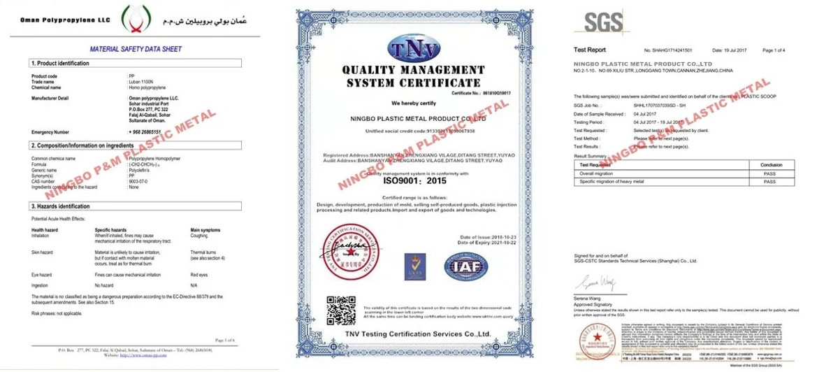

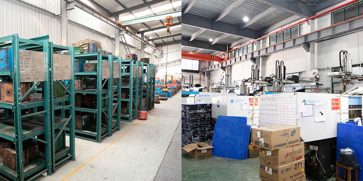
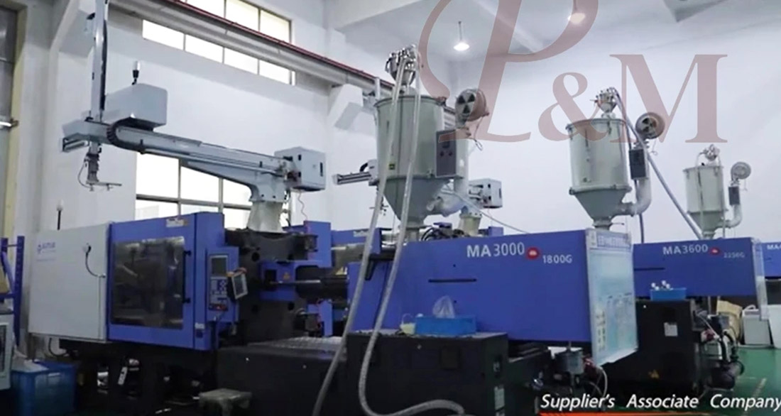
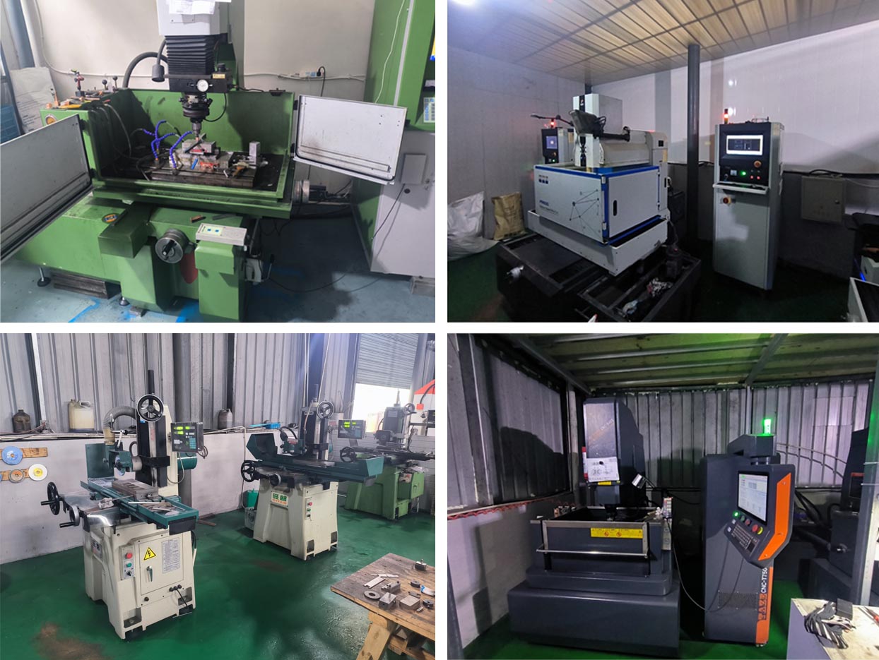
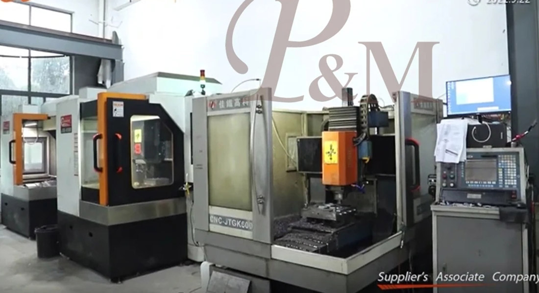
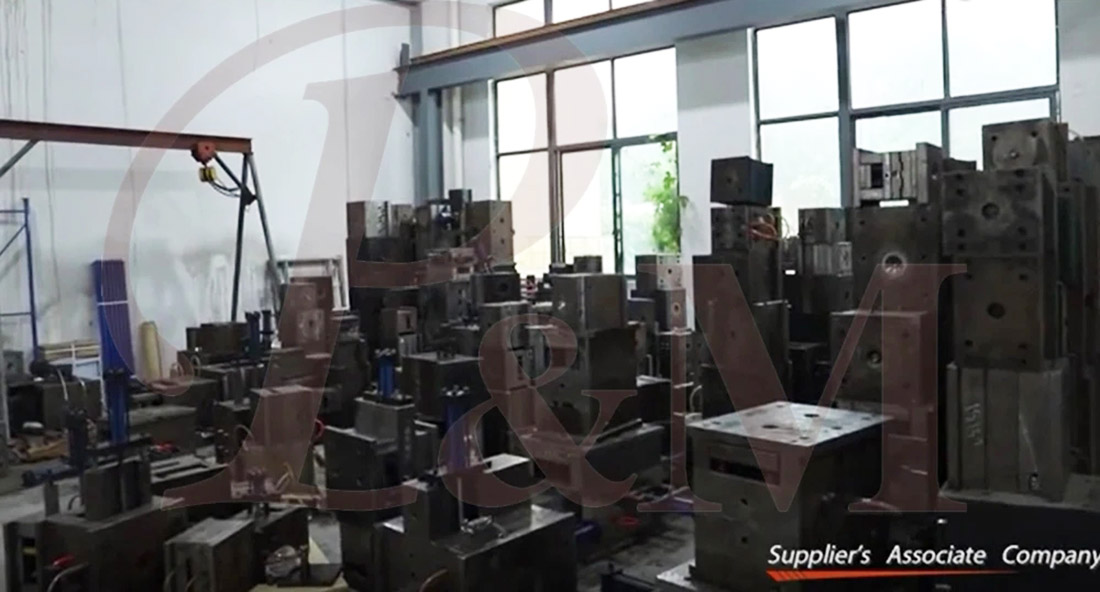
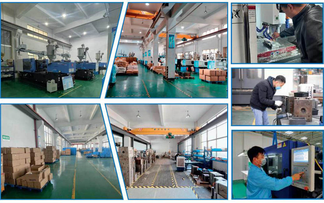
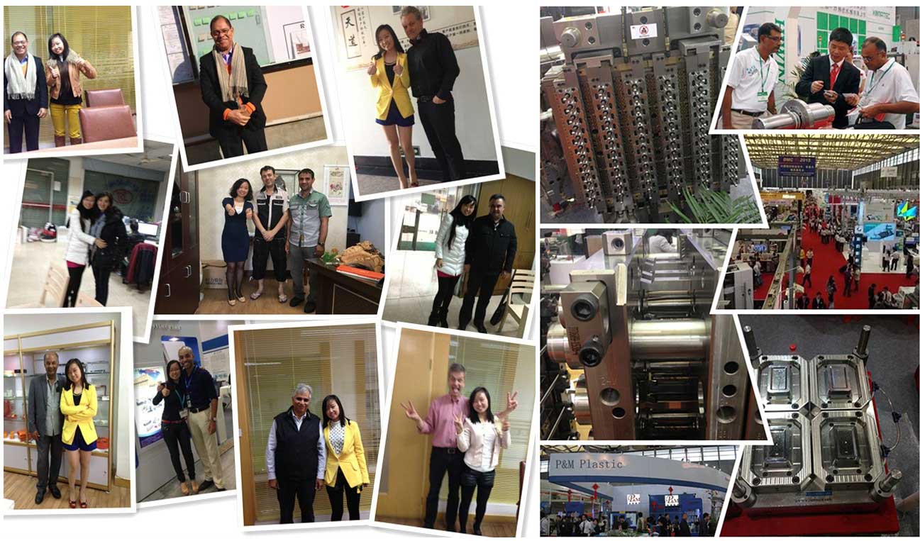
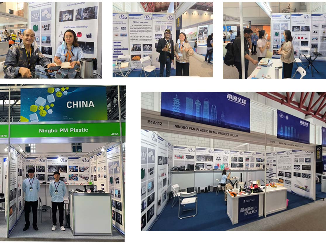
We always adhere to the principles of quality first and time first. While providing customers with the highest quality products, try to maximize the production efficiency and shorten production time. We are proud to tell every customer that our company has not lost any customer since its establishment.If there is a problem with the product, we will seek a solution actively and take responsibility to the end.

FAQ
Q1: Are you trading company or manufacturer ?
A: We are manufacturers.
Q2. When can I get the quotation?
A: We usually quote within 2 days after we get your inquiry.
If you are very urgent, please call us or tell us in your email so that we can quote for you first.
Q3. How long is the lead-time for mold?
A: It all depends on the products' size and complexity. Normally, the lead time is 25 days.
Q4. I have no 3D drawing, how should I start the new project?
A: You can supply us a molding sample, we will help you finish the 3D drawing design.
Q5. Before shipment, how to make sure the products quality?
A: If you don't come to our factory and also don't have the third party for inspection, we will be as your inspection worker.
We will supply you a video for production process detail include process report, products size structure and surface detail, packing detail and so on.
Q6. What is your payment terms?
A: Mold Payment: 40% deposit by T/T in advance, 30% second mold payment before sending out the first trial samples, 30% mold balance after you agree the final samples.
B:Production Payment: 50% deposit in advance, 50% before sending out the final goods.
Q7: How do you make our business long-term and good relationship?
A:1. We keep good quality and competitive price to ensure our customers benefit for best quality products.
2. We respect every customer as our friend and we sincerely do business and make friends with them, no matter where they come from.
Hot Tags: Customization of Button Device Parts moulding, China, Manufacturer, Supplier, Factory, Customized, Wholesale, Buy, Quality, Latest Selling, Made in China
Related Category
Send Inquiry
Please feel free to give your inquiry in the form below. We will reply you in 24 hours.