
Home
>
Product > Core Customization Service > Custom Molding > Steam Guide and Functional Components moulding
Product
- Core Customization Service
- Health Care
- Electronic Appliances and Instruments
- Maternal and Child Supplies Molds
- Recreational Sports
- Home Furnishing Art
- Auto Accessories
- Transportation and Warehousing
- Lighting Fixtures
- Construction Equipment
- Packaging Product
- Educational & Laboratories
- Clothing Luggage Accessories
- Care and Cleaning Products
- Agriculture & Forestry
- Mechanical Equipment
- Pet Supplies
- Kitchenware
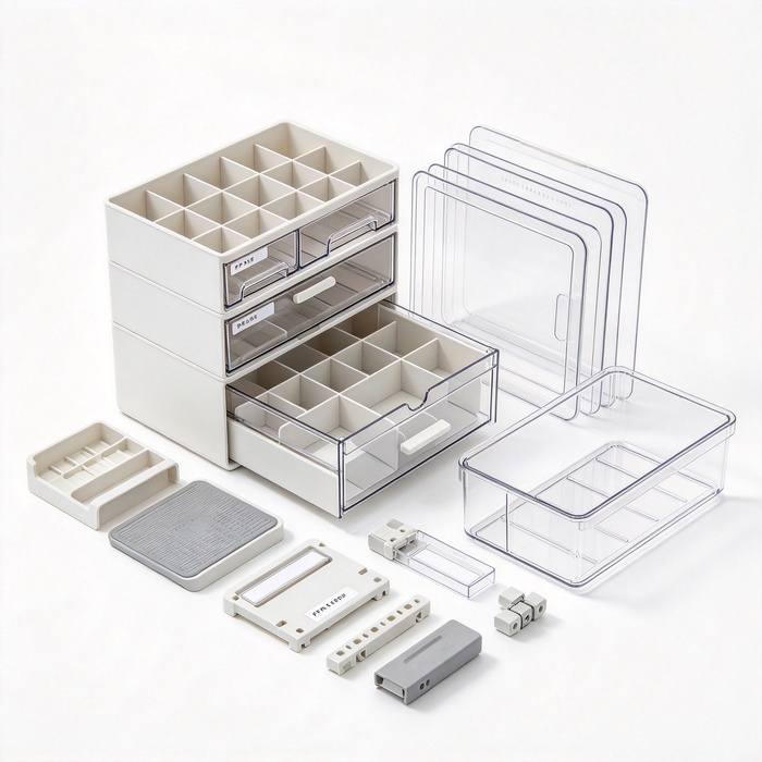
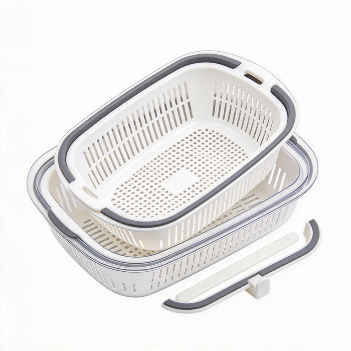
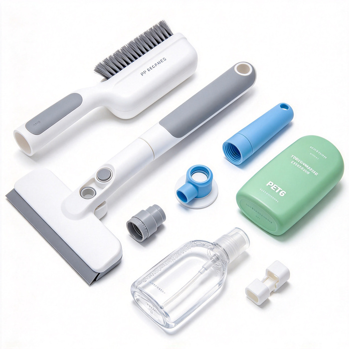
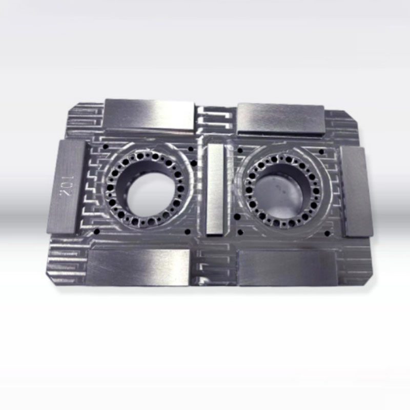
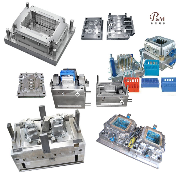
Steam Guide and Functional Components moulding
Ningbo (P&M) Plastic Metal Products Co., Ltd. has 17 years of mold manufacturing technology and can customize Steam Guide and Functional Components moulding. We provide professional customized Steam Guide and Functional Components moulding services, and we are a professional Steam Guide and Functional Components moulding manufacturer. We have sufficient experience in selecting product raw materials and mold materials. In the process of customizing Steam Guide and Functional Components moulding, our factory can provide one-stop service. We have design and production capabilities related to Steam Guide and Functional Components moulding, such as: CAD design, mold manufacturing, injection molding, plastic product production, assembly and other technologies.
Send Inquiry
Product Description
In addition, our company has established cooperative relationships with plastic raw material suppliers, printing manufacturers, etc. to ensure the supply of raw materials and printing quality. Through our rich experience and perfect supply chain, our company can provide customers with high-quality customized Steam Guide and Functional Components moulding products to meet their specific needs. At the same time, we have 10 years of professional foreign trade service experience, understand the foreign trade process, and better serve our customers. For Steam Guide and Functional Components moulding products, we can make corresponding plastic parts, which is mainly done through injection molds.
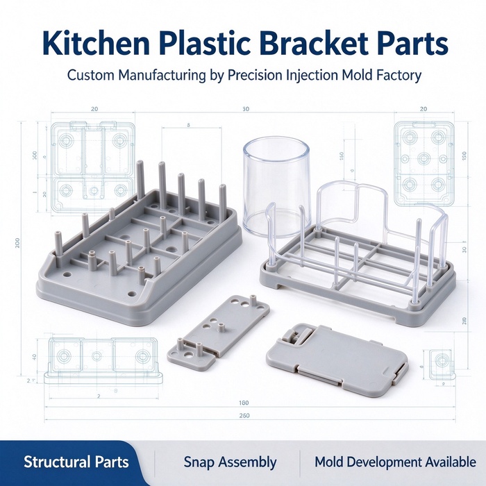

## I. Material Selection (Based on Steam Load)
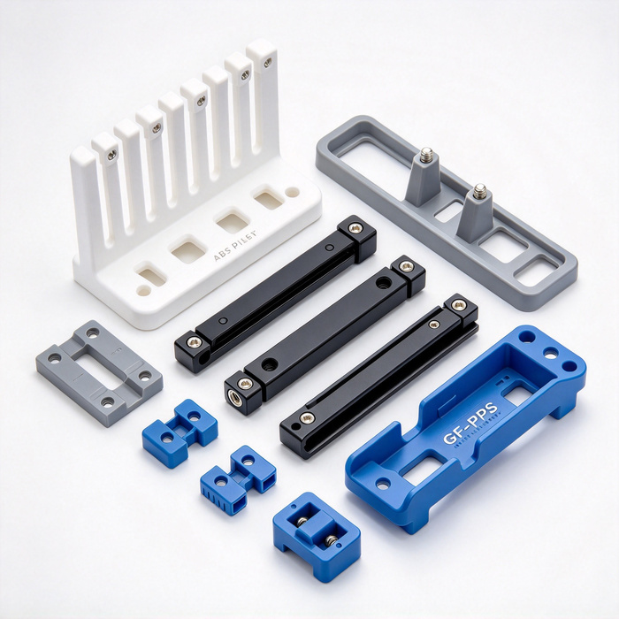
1. **PPS GF (Glass Fiber Reinforced – Mainstream for Mass Production)**
Suitable for: Steam-guiding grids, flow distribution plates, steam collection chambers, condensate drainage ribs, and steam nozzle bases.
✅ Advantages: Resistant to saturated steam (100–160°C), oils, and cleaning agents; stable crystallization; controlled creep; good flowability (ideal for thin-walled, multi-aperture parts); more cost-effective than PPSU.
⚠️ Risks: Potential for glass fiber orientation and "fiber floating" (surface exposure); significant loss of strength at weld lines; cannot achieve high light transmission; areas with exposed glass fibers are prone to accumulating oil and scale due to long-term steam exposure.
2. **PPSU**
Suitable for: Precision steam nozzles, thin steam-distribution plates, components subject to frequent disassembly or alternating stress, and steam-guiding parts located near viewing windows.
✅ Advantages: Superior hydrolysis resistance compared to PPS; high toughness; resistant to stress cracking; offers semi-transparency; no issues with glass fiber exposure or scale accumulation.
⚠️ Risks: High viscosity makes mold filling difficult; extremely sensitive to drying conditions and mold temperature (internal stress is a major failure factor); high unit cost.
3. **PESU**
Suitable for: Commercial high-temperature steam ovens designed for continuous operation. Offers better steam and hydrolysis resistance than PSU (falling between PPSU and PSU); features a narrow molding process window.
4. **Platinum-Cured LSR (Liquid Silicone Rubber)**
Used for: Steam sealing rings, steam cushioning pads, and flexible limiters for nozzles. (Note: Must be platinum-cured, not peroxide-cured.)
>
> ❌ Strictly Prohibited: Standard PA66-GF (highly susceptible to steam-induced hydrolysis), PC, PCTG, PETG, and standard POM. ## II. DFM Considerations (Steam-Directing Components – Key Differences from Standard Structural Parts)
Design Objectives: Stable flow field; resistance to water/oil accumulation; effective mold filling; and durability against cracking during hygrothermal (moisture-heat) cycling.
### 1. Flow Channels, Steam-Directing Holes, and Nozzles
- Steam-directing and discharge holes should preferably be circular. For square holes, corners must have a radius (R) ≥ 0.4 mm; sharp, right-angled corners can cause eddy currents, oil accumulation, and the initiation of cracks.
- Small holes should ideally have a diameter ≥ 1.8 mm. For smaller diameters, use dedicated insert pins. Ensure a radius at the base of small holes rather than leaving sharp, "clean" (unfilleted) corners.
- Hole Arrays: Maintain a spacing of ≥ 1.5× the hole diameter to prevent excessively thin ribs or the clustering of weld lines. For components with multiple holes, perform coupled mold-flow and fluid-dynamics simulations to ensure both balanced plastic filling and uniform steam distribution.
- Nozzle Inclination: Align the nozzle slope with the direction of steam flow. Incorporate a slight incline to allow condensed water to flow back along the walls, preventing the formation of hanging droplets at the nozzle exit.
### 2. Drainage, Flow-Directing Ribs, and Water-Collection Channels
- All flow-directing surfaces must feature a continuous, unidirectional slope (≥ 3°) to prevent water from pooling on flat sections. Stagnant water leads to prolonged exposure to moisture and heat, accelerating hydrolysis, mold growth, and oil accumulation.
- Rib bases must have a radius (R) ≥ 0.5 mm. Rib thickness should be 40%–50% of the nominal wall thickness; excessive thickness can lead to sink marks and internal stress.
- Water-Collection Channels: Use a rounded (arc-shaped) bottom profile. Avoid V-shaped, sharp-bottomed channels, as these tend to trap oil and are difficult to clean. ### 3. Wall Thickness Control
Baseline wall thickness: 1.6–2.2 mm for PPS-GF; 1.8–2.5 mm for PPSU.
Thin-walled steam distribution plates can go as low as 1.4 mm, provided that the mold temperature is sufficiently high and the gate layout is balanced.
**Avoid localized thick sections:** Thick areas can trap steam internally; subsequent thermal cycling may cause "implosive" micro-cracking.
### 4. Weld Lines (Highest Risk Area for This Type of Component)
Steam-guiding components almost invariably feature multiple gates and apertures, making weld lines unavoidable. Mandatory rules:
- ❌ Weld lines must not be located in: primary steam-scouring zones, areas surrounding steam discharge ports, load-bearing sections of flow-guiding ribs, or the bottoms of condensate drainage channels.
- ✅ Direct weld lines toward areas with low pressure, low flow velocity, and minimal mechanical load. If necessary, incorporate overflow wells to remove the weakened material at the weld interface.
- Weld line strength reduction is particularly pronounced in glass-fiber-reinforced materials. If a weld zone must withstand steam impingement, consider switching to PPSU.
### 5. Fillets, Hygiene, and Parting Lines
- Surfaces in contact with food or subject to steam scouring: R ≥ 1.0 mm.
- Parting lines and insert seams should, as much as possible, avoid primary airflow paths. If unavoidable, ensure parting line misalignment is ≤ 0.03 mm and polished smooth. Ensure insert seams are oriented to prevent water/residue accumulation.
- Gap specifications: Gaps should be either < 0.5 mm or > 3 mm to avoid narrow crevices that could trap grease, oil, or food residue.
### 6. Draft Angles and Fiber Orientation Control
- PPS-GF: ≥ 2°; PPSU (visible surfaces or surfaces subject to steam scouring): ≥ 2.5°.
- For grilles and thin-walled flow-guiding components: Glass fiber orientation can induce warpage. Optimize gate placement so that glass fibers align with the direction of structural support, rather than running transversely across thin sections; otherwise, heating may cause the grille to distort and the airflow to deviate from its intended path. ### 7. Assembly Clearances (Compensation for Thermal Expansion)
For components such as steam nozzles, steam distribution plates, and steam chambers, allowances for thermal expansion must be factored in during assembly at room temperature. Materials like PPS and PPSU exhibit anisotropic thermal expansion—a characteristic particularly pronounced in glass-fiber-reinforced grades. Insufficient clearance can lead to jamming upon heating, deformation of air/steam channels, or uneven steam distribution.
## III. Key Points for Mold Design
1. **Steel Selection**
- PPS-GF: Use SKD61 or 8407 (hardened to HRC 48–52) for wear and erosion resistance. Since high-velocity glass-fiber-reinforced resin can cause the polish on cavity surfaces to degrade over time, allow for periodic re-polishing.
- PPSU / PESU: Use S136H with a mirror or fine-polished finish to minimize resin adhesion and reduce potential stress concentrators.
2. **Gating System**
- For multi-aperture distribution plates or large-scale steam distribution plates, use a valve-gated hot runner system to ensure balanced filling through multiple injection points.
- Gate Types: Prefer fan gates or side gates; avoid small pin-point gates, as they induce high shear, cause significant glass-fiber orientation, and lead to severe "fiber floating" (surface exposure of fibers).
- Gate Placement: Avoid areas near steam nozzles, flow-directing inclined surfaces, or drainage bases. Ensure that gate vestiges do not interfere with airflow or the return flow of condensed water.
3. **Heating / Cooling (High-Temperature Oil-Based Mold Temperature Controllers)**
- PPS: 130–160°C; PPSU: 150–180°C.
- Provide dedicated oil circuits for slender pins, multi-aperture inserts, and thin grid structures to ensure uniform mold temperature across the entire cavity. Localized low temperatures can result in weak weld lines, concentrated internal stress, and fiber floating.
- Install thermal insulation plates on the mold base/plates to minimize heat loss and stabilize the mold temperature. 4. **Venting (Crucial)**
Provide dedicated venting at grids, the ends of apertures, the ends of ribs, and weld line locations;
- PPS: 0.010–0.015 mm
- PPSU / PESU: 0.008–0.012 mm
Trapped air can lead to short shots at apertures, material scorching, and a drastic reduction in weld line strength—causing the part to crack along the weld line shortly after being put into service due to steam impingement.
5. **Ejection System**
Avoid single-point rigid ejection for thin grids or multi-aperture plates; instead, use ejector blades, flat pins, or sleeve ejectors to distribute the force. Ensure that ejector marks are kept away from surfaces exposed to steam flow. Since the material’s toughness decreases at high temperatures, reduce the speeds for mold opening and ejection.
6. **Insert Management**
Implement anti-rotation and anti-loosening features for the slender inserts used to form steam apertures. Under long-term exposure to high-temperature cycling, any loosening or shifting of these inserts will directly alter the steam injection angle. Ensure that insert seams are not positioned on surfaces subject to the primary steam flow.
We are a Steam Guide and Functional Components moulding manufacturer, providing high-quality Steam Guide and Functional Components moulding manufacturing. As long as you want to customize/develop Steam Guide and Functional Components moulding products, you can find us. We have professional injection mold design and mature manufacturing technology, providing you with one-stop service, from product design-mold making-product production-product packaging-product transportation, we can help you in every link. As long as you come to us, we will provide you with the ultimate service and satisfy you in terms of product quality, production time, information dialogue, etc.
|
Product Name |
Treadmill moulding |
|
Pls provide |
2D, 3D, samples, or the size of the multi-angle pictures |
|
Mould Time |
20-35 Days |
|
Product time |
7-15 Days |
|
Mould precision |
+/-0.01mm |
|
Mould life |
50-100 million shots |
|
Producing Process |
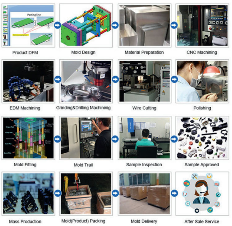
Audit drawings - mold flow analysis - design validation - Custom Materials - mold processing - core processing - electrode machining - Runner system processing - parts processing and procurement - machining acceptance - cavity surface treatment process - complex mode Die - The entire mold surface coating - Mounting plate - mold sample - sample test - sending samples |
|
Mould cavity |
One cavity, multi-cavity or same different products be made together |
|
Mould material |
P20,2738,2344,718,S136,8407,NAK80,SKD61,H13 |
|
Runner system |
Hot runner and cold runner |
|
Base material |
P20,2738,2344,718,S136,8407,NAK80,SKD61,H13 |
|
Finish |
Pitting the word, mirror finish, matte surface, striae |
|
Standard |
HASCO, DME or dependent upon |
|
Main technology |
Milling, grinding, CNC, EDM, wire cutting, carving, EDM, lathes, surface Finish, etc. |
|
Software |
CAD,PRO-E,UG Design Time: 1-3 days (normal circumstances) |
|
Product material |
ABS,PP,PC,PA6,PA66,TPU,POM,PBT,PVC,HIPS,PMMA,TPE,PC/ABS,TPV,TPO,TPR,EVA,HDPE,LDPE,CPVC,PVDF,PPSU.PPS. |
|
Quality system |
ISO9001:2008 |
|
Establish time |
20days |
|
Equipment |
CNC,EDM,Cutting off Machine,plastic machinery,etc plastic suitcase mould zhe jiang |
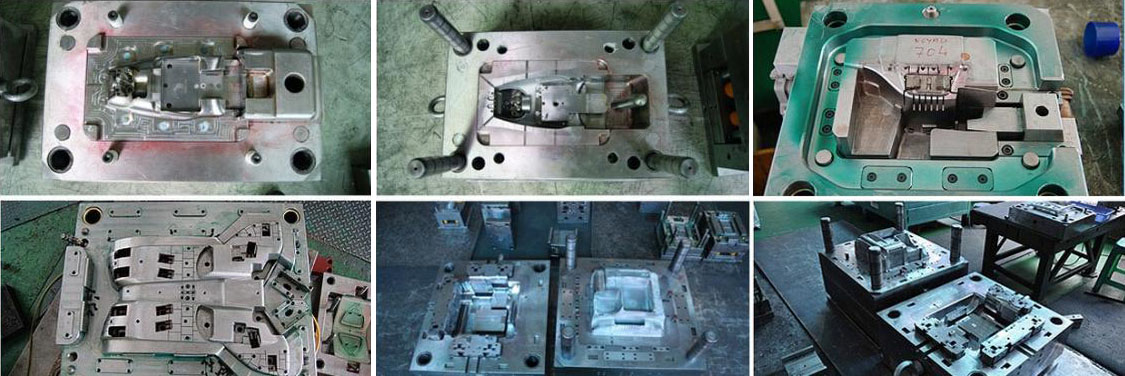
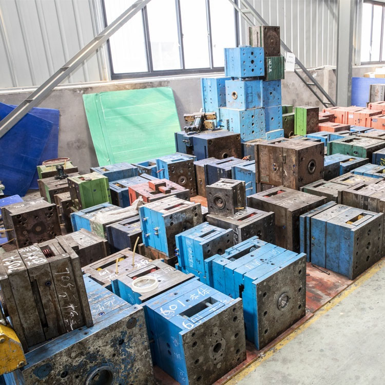
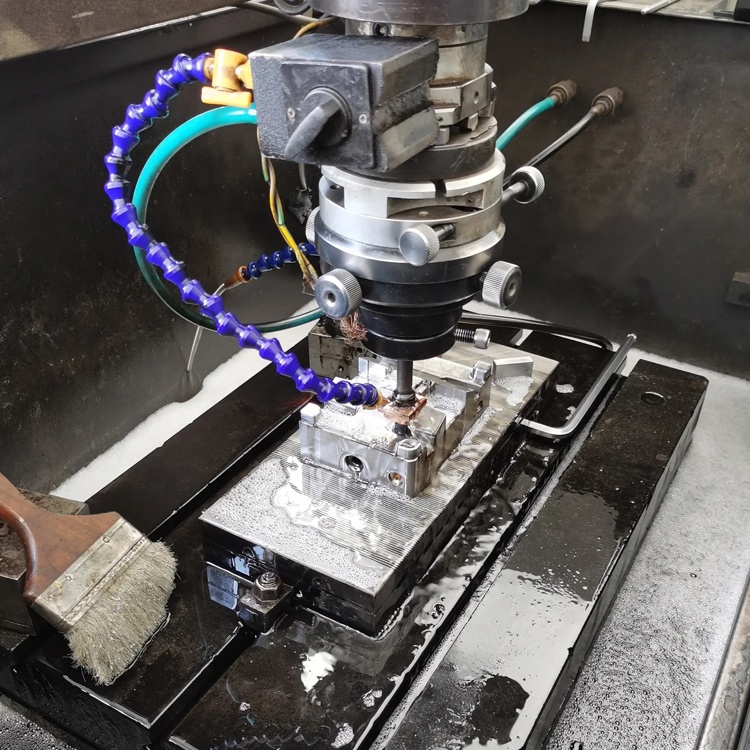
Plastic Injection Mould making
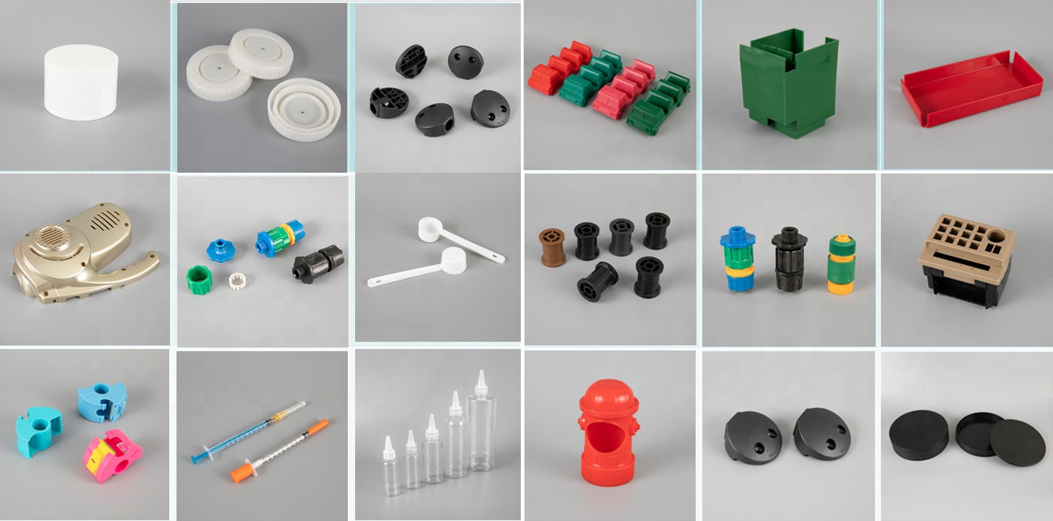
Plastic molding specifications
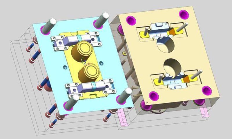
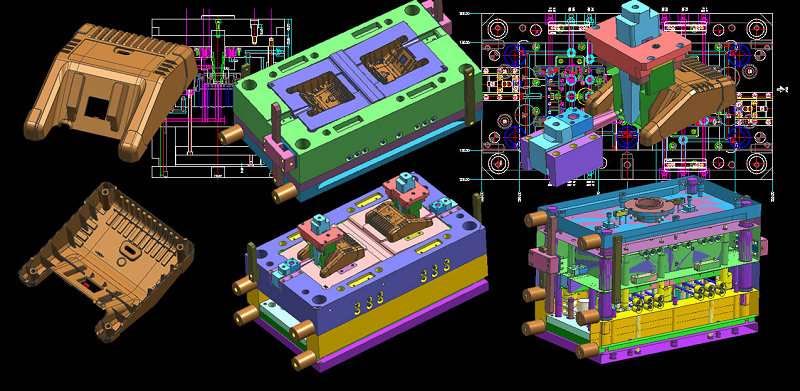
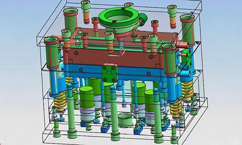
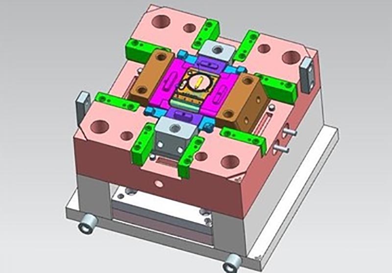
Mold design:
Transaction process:
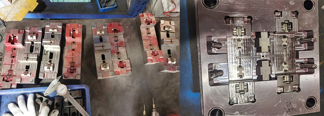
Mold testing:

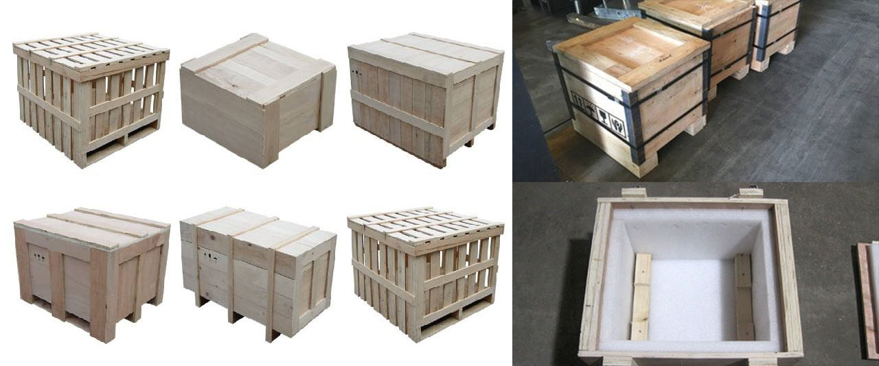
Product packaging
Factory
We are Custom Plastic Mold factory. Our factory is plastic injection mold maker. we has 17 years of experience in professional custom plastic mold and 10 years of foreign trade experience. We are custom Plastic Mold supplier. We can provide custom Plastic Mold service. Our factory can make the Injection molded plastic parts, and the quality of the products will satisfy you.
We have more than 50 high-end machines and hundreds of engineers and designers. We can provide one-stop service, from product design - mold making - product production - product packaging - transportation. We have a complete production chain. We can meet all your requirements.
Services we provide:
Professional custom mold service, Plastic mold design and manufacturing .plastic product production, product design, mold design, blow mold customization, rotational mold customization, die-casting mold customization. 3D printing services, CNC manufacturing services, product packaging, customized packaging, shipping services.
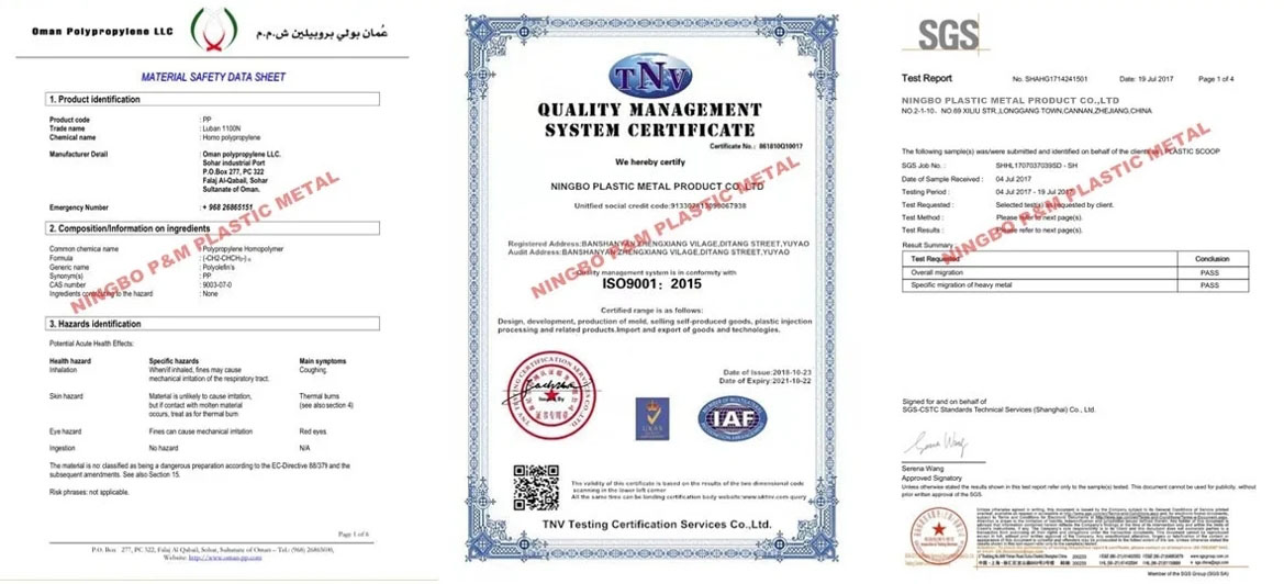

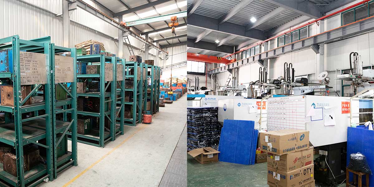
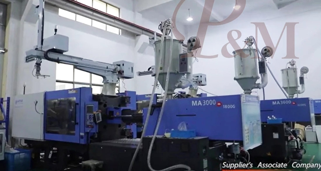
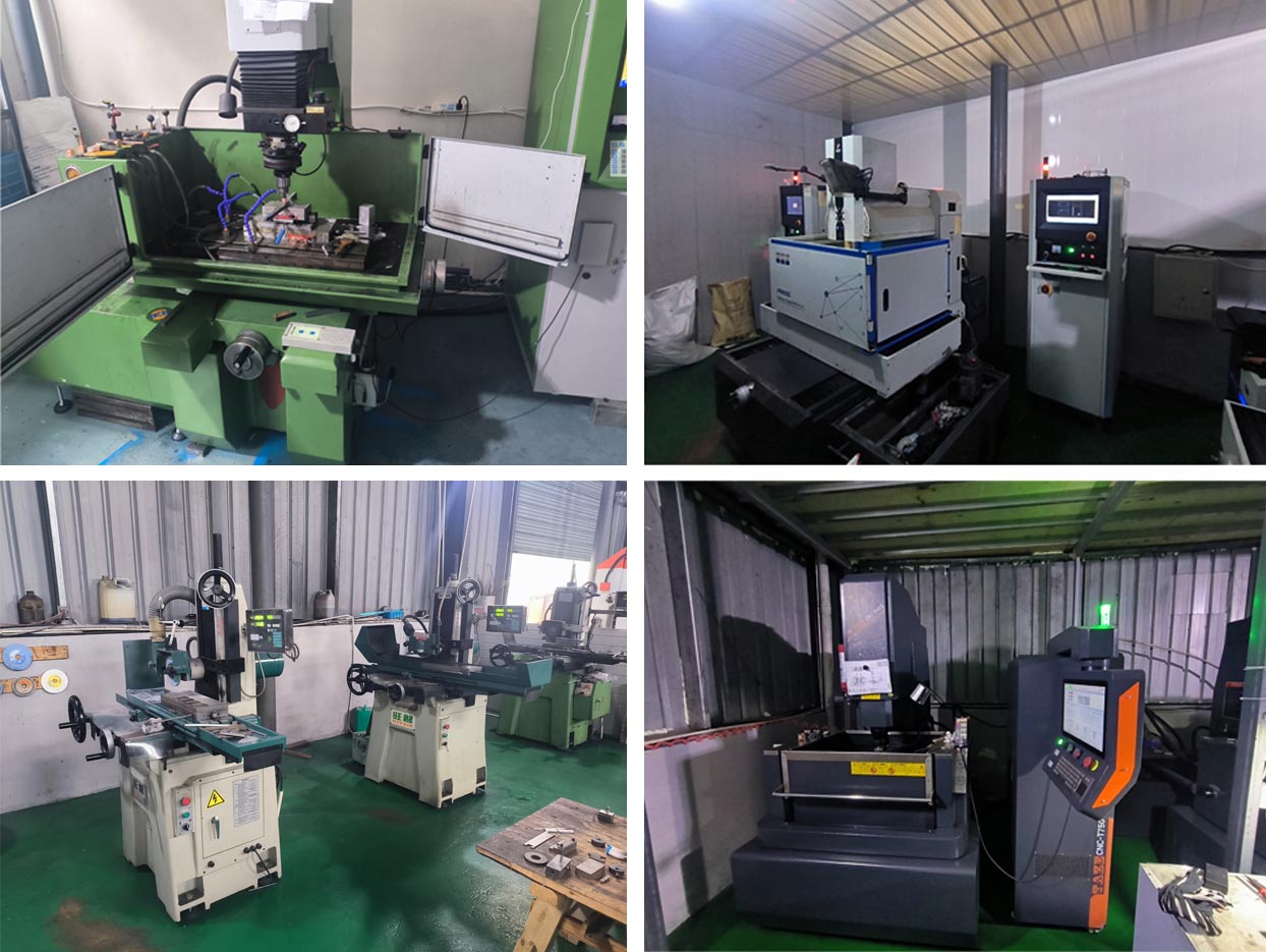
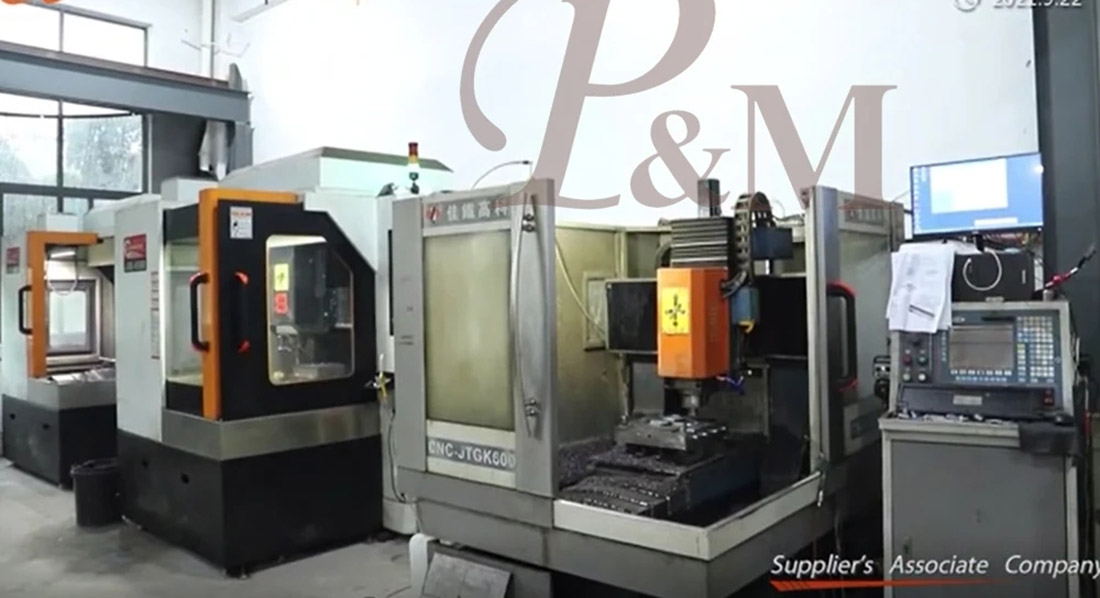
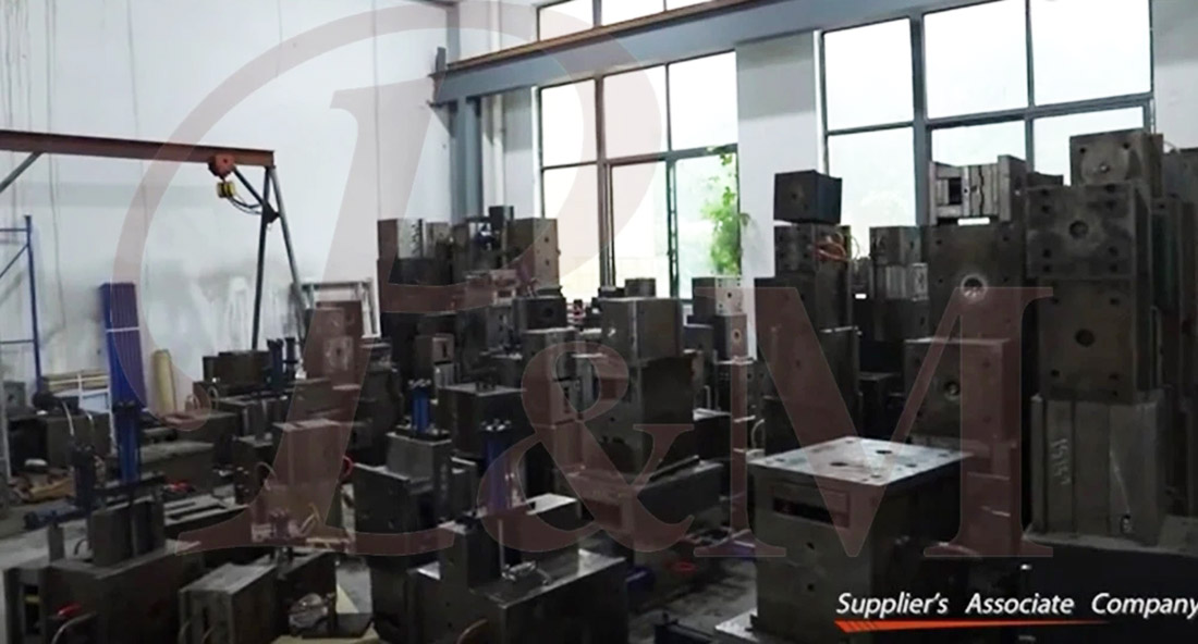
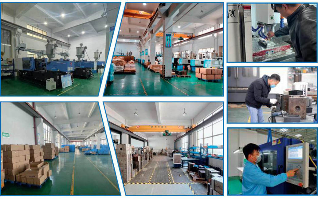

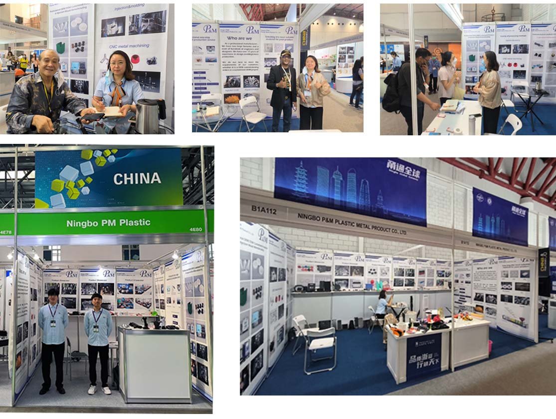
We always adhere to the principles of quality first and time first. While providing customers with the highest quality products, try to maximize the production efficiency and shorten production time. We are proud to tell every customer that our company has not lost any customer since its establishment.If there is a problem with the product, we will seek a solution actively and take responsibility to the end.

FAQ
Q1: Are you trading company or manufacturer ?
A: We are manufacturers.
Q2. When can I get the quotation?
A: We usually quote within 2 days after we get your inquiry.
If you are very urgent, please call us or tell us in your email so that we can quote for you first.
Q3. How long is the lead-time for mold?
A: It all depends on the products' size and complexity. Normally, the lead time is 25 days.
Q4. I have no 3D drawing, how should I start the new project?
A: You can supply us a molding sample, we will help you finish the 3D drawing design.
Q5. Before shipment, how to make sure the products quality?
A: If you don't come to our factory and also don't have the third party for inspection, we will be as your inspection worker.
We will supply you a video for production process detail include process report, products size structure and surface detail, packing detail and so on.
Q6. What is your payment terms?
A: Mold Payment: 40% deposit by T/T in advance, 30% second mold payment before sending out the first trial samples, 30% mold balance after you agree the final samples.
B:Production Payment: 50% deposit in advance, 50% before sending out the final goods.
Q7: How do you make our business long-term and good relationship?
A:1. We keep good quality and competitive price to ensure our customers benefit for best quality products.
2. We respect every customer as our friend and we sincerely do business and make friends with them, no matter where they come from.
Related Category
Send Inquiry
Please feel free to give your inquiry in the form below. We will reply you in 24 hours.